36
ML-5120A
2. Name and Function of Each Section on the Top Side
(5) POWER Lamp
When the MAIN POWER switch is turned ON, the POWER lamp
comes on so that the operator can check that the power supply has
been turned ON.
(6) SHUTTER Lamp
(1 to 2)
Stay(s) on while some (one) of the branch units 1 to 2 are (is) open.
(7) READY Lamp
Lights up when the LD is turned on for outputting the laser.
(8) LASER Lamp
Indicates that laser is being output.
(9) Cooler Unit
(Option)
Cools the inside of the main unit. Select this unit when used in condi-
tions of high power and high temperature.
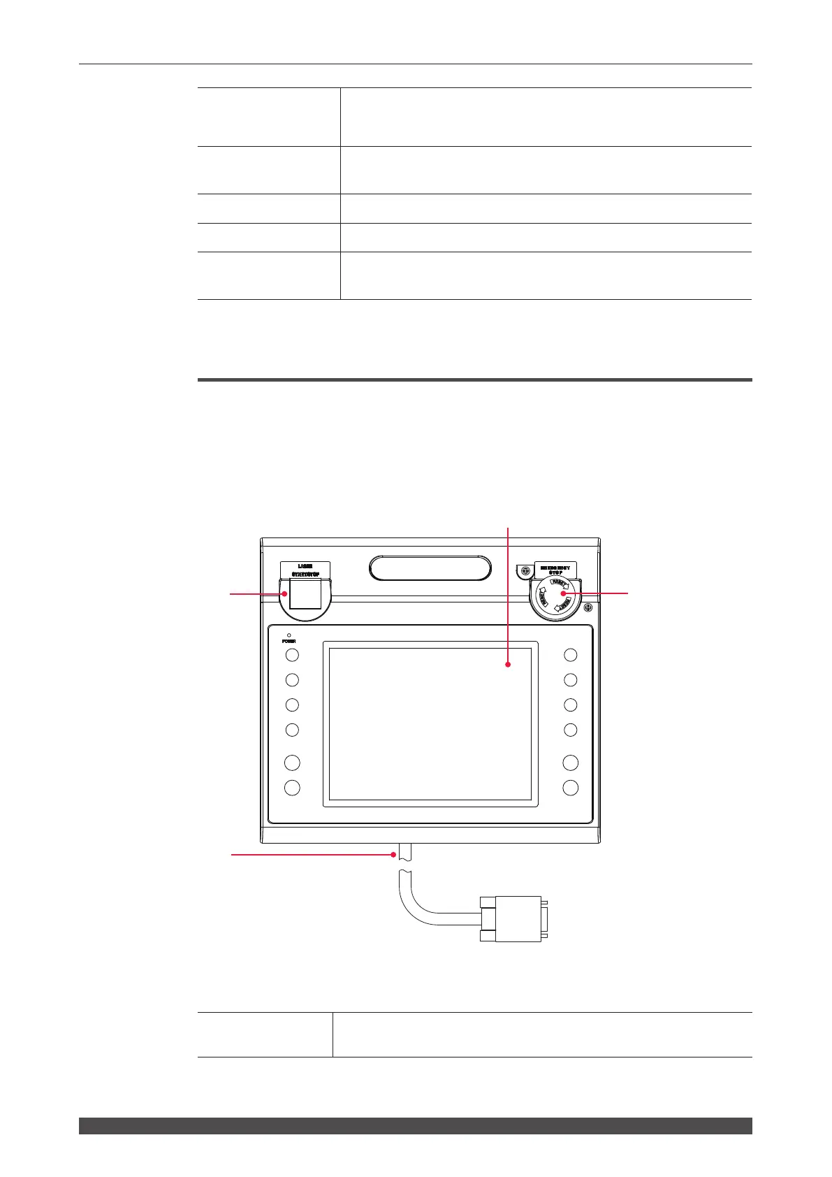
Laser Controller (MLE-122A)
In the following, the buttons and keys of the laser controller are explained.
The laser controller is accommodated in the control panel on the top surface of the
main unit and used to set processing conditions and performs operations to output
laser light. If the laser controller is dismounted from the main unit, operations can be
performed in a place remote from the laser equipment.
Function of Each Section on the Laser Controller
(1)
Liquid Crystal
Display
Displays the setting conditions and monitor data.
(3) (2)
(1)
(4)
 Loading...