4. Programming
149
ML-5120A
Chapter 4 Laser Processing by External Input/ Output Signals (EXTERNAL CONTROL)
Introduction Part Operating Part Maintenance Part Appendixes
Installation and
Preparation Part
4. Programming
This section explains the precautions for programming laser processing by ex-
ternal input/output signals (EXTERNAL CONTROL).
The timing chart of the appendix shows the input signal length and input waiting time
required to correctly operate the laser. Perform actual programming referring to this
timing chart.
In the following, a control ow is explained by taking the case where "Schedule 1" is
rst specied and then "Schedule 2" is specied to perform a single laser light output
from the branch unit 1, as an example.
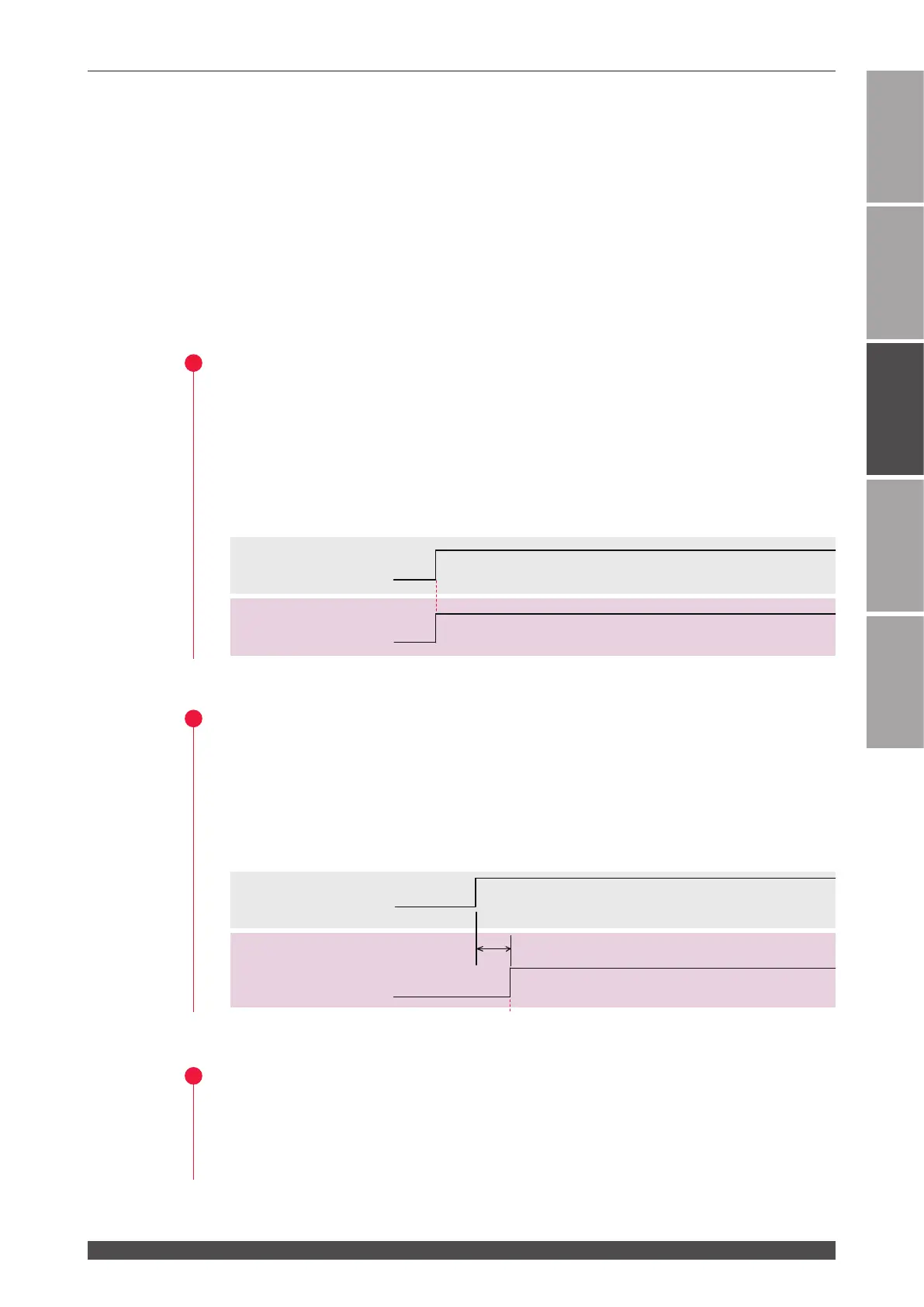
1
Switching the Control Method
(1) Put pin No.25 (control switching) of the EXT. I/O (1) connector in a closed circuit.
Pin No.23 of the EXT. I/O (1) connector is put in a closed circuit and the signal
(external input acceptable) is returned from the laser.
⇒
Press the “STATUS” button on the laser controller to display the STATUS screen.
Then, you can confirm that "EXTERNAL CONTROL" is selected as the control
method.
2
Turning ON the LD Power Supply
(1) Put pin No.4 of the EXT. I/O (1) connector in a closed circuit to turn ON the LD
power supply.
Pin No.13 of the EXT. I/O (1) connector is put in a closed circuit after 5 seconds
maximum and the signal (LD power supply preparation) is returned from the la-
ser.
3
Opening the Safety Shutter
(1) Put pin No.15 of the EXT. I/O (2) connector in a closed circuit to open the safety
shutter.
The corresponding SHUTTER lamp comes on.
ON
OFF
LD power supply
prereparation output
LD power supply
ON/OFF input
External input
acceptable output
5s max.
ON
OFF
ON
OFF
Control switching
input
LD power supply
prereparation output
LD power supply
ON/OFF input
External input
acceptable output
↓
 Loading...