3. Connector Functions
135
ML-5120A
Chapter 4 Laser Processing by External Input/ Output Signals (EXTERNAL CONTROL)
Introduction Part Operating Part Maintenance Part Appendixes
Installation and
Preparation Part
⇒
When there is inuence of noise, attach a ferrite core as close to the equipment
as possible. A ferrite core has an eect in reducing external noise.
⇒
Do not connect the shield of a cable to SG (signal ground).
3. Connector Functions
Pin Arrangement and Functions
There are 4 connectors to be connected for the control by external input/out-
put. This section explains the arrangement and functions of the respective
pins.
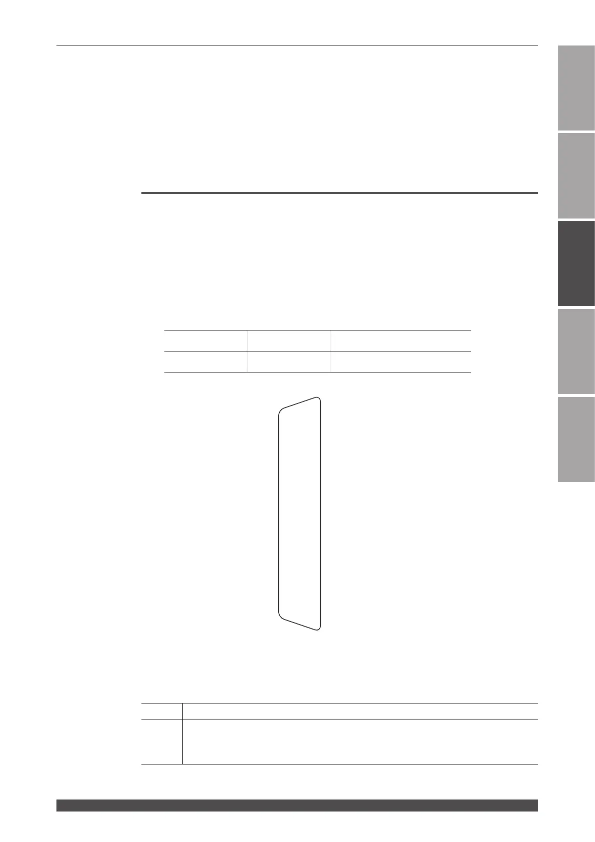
EXT. I/O (1) Connector (D-Sub 25 pin)
The EXT. I/O (1) connector inputs or outputs the start signal of guide light and
laser light.
⇒
Use the following product out of the attached connectors.
Plug Case Manufacturer
HDBB-25P(05) HDB-CTH(10) HIROSE ELECTRIC CO., LTD.
Input Pins of EXT. I/O (1) Connector
⇒
Close pin No.25.
Pin No. Description
1
+24 V OUT
Power supply for external input signals. This pin is exclusively used for the ML-5120A.
Do not use it for any other purpose.
13
12
11
10
9
8
7
6
5
4
3
2
1
25
24
23
22
21
20
19
18
17
16
15
14
CONTROL CHANGEOVER (in)
External input receivable (out)
End (out)
Output COM
Monitor trouble (out)
0V OUT
Monitor normal (out)
Trigger (out)
Laser output (out)
Trouble (out)
(out) Ready
(out) LD power supply preparation
Input COM
(in) Old emergency stop (LASER STOP)
(in) TROUBLE RESET
(in) Guide beam
(in) LD power supply ON/OFF
(in) LASER STOP
(in) LASER START
+24V OUT
 Loading...