50
ML-5120A
2. Connecting the Optical Fiber
2. Connecting the Optical Fiber
This section explains the method of connecting the optical ber on the laser
beam output unit side.
WARNING
■ Be sure to receive education for this work from our engineer.
■ Before starting work, be sure to turn OFF the power supply.
⇒
Do not disconnect the optical ber on the laser beam branch unit side. When
disconnecting it, contact us for information.
Before Connection
Before making a connection, check the end face of the optical ber. If it is stained or
dust is attached, blow it o by air blow or wipe it out with lens cleaning paper.
⇒
For a check for stain, use the optional end face checker.
⇒
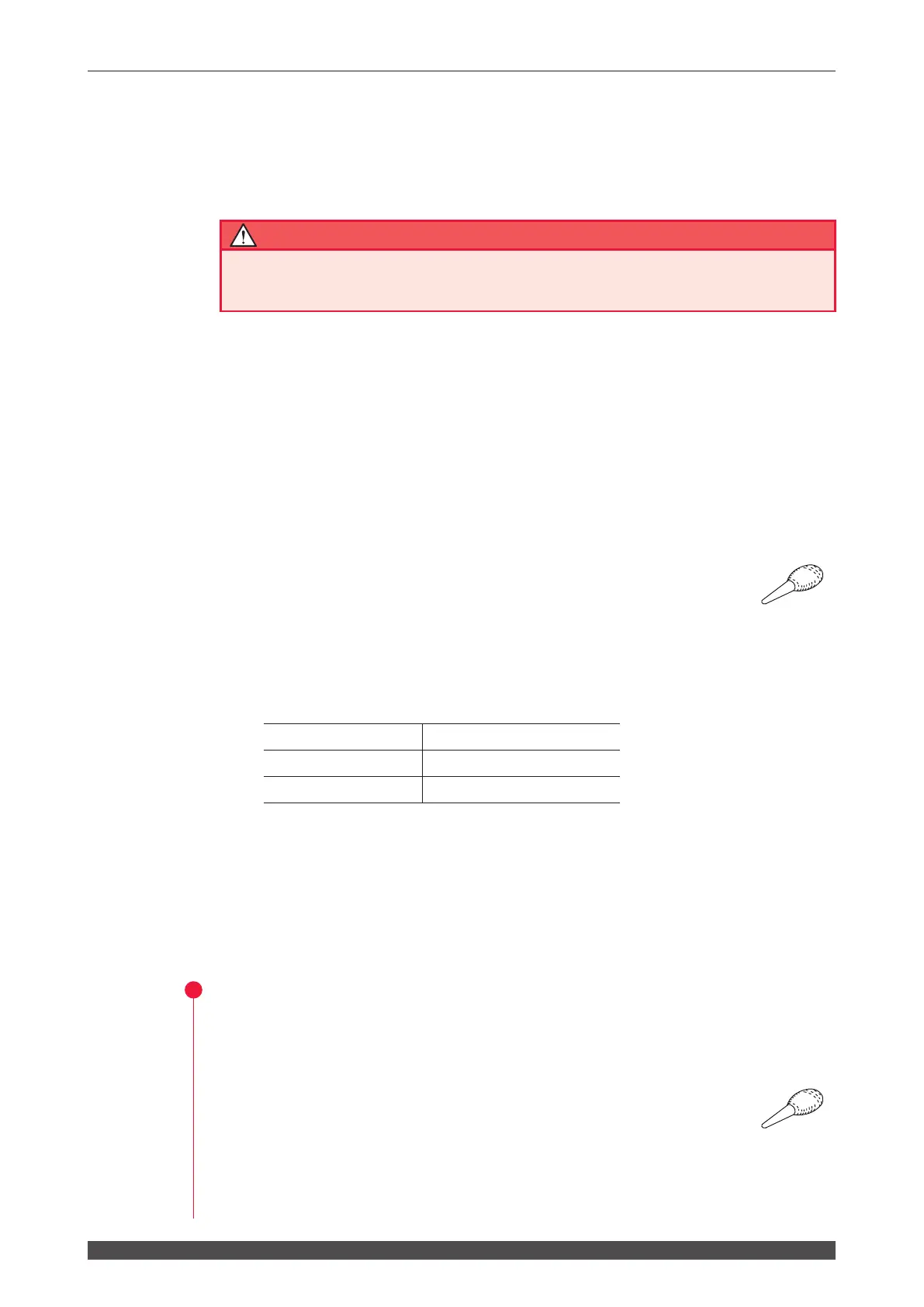
Use such an air blow dedicated to cameras as shown at right. If rubber is
deteriorated, dust may enter the optical ber. Use a clean air blow.
Precautions during Operation
⇒
During operation, take care not to give shocks to the optical ber or bend it below
the minimum bending radius (in the following table).
Minimum bending radius of the optical ber
Core Diameter Minimum Bending Radius
φ 0.2, 0.3, 0.4 mm 100 mm
φ 0.6 mm 150 mm
⇒
Do not tighten the nut of ber plug too rmly; otherwise the incident laser beam
may be dislocated. Tighten the nut by hand without using a tool.
Item required
Air blow
Operation Procedure
(1) Remove the cap at the end of the optical ber and blow o dust by using the air
blow.
⇒
Use such an air blow dedicated to cameras as shown at right. If rubber is
deteriorated, dust may enter the optical ber. Use a clean air blow.
(2) Insert the key provided on the optical ber plug along the groove on the output
unit side.
 Loading...