3. Connector Functions
145
ML-5120A
Chapter 4 Laser Processing by External Input/ Output Signals (EXTERNAL CONTROL)
Introduction Part Operating Part Maintenance Part Appendixes
Installation and
Preparation Part
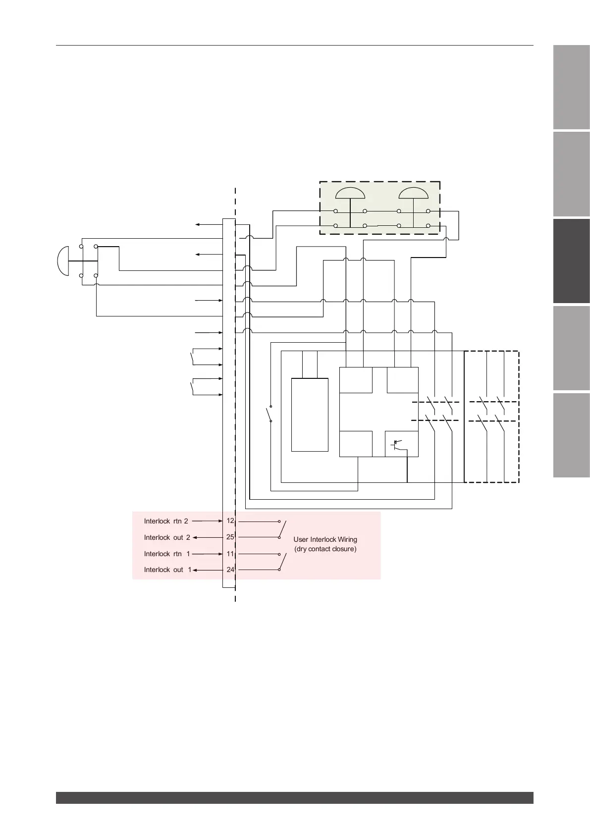
In this wiring example a Pilz PNOZ family safety relay module controls the Laser and
interfaces two external emergency stop buttons. In this example the Pilz device would
also control additional emergency stop functions outside of the Laser using expan-
sion contacts. The more devices which must be implemented the more expansion
contacts must be added to the Safety Relay Module. Any suitable IEC13849-1 com-
pliant safety relay controller is acceptable as long as it is implemented in this manner.
The end user is responsible for verifying compliance of the machine as a whole.
User ESTOP Wiring
ESTOP
Power
A1 A2
Pilz PNOZ s3
Safety Relay
Module
750103
Input Input
Reset/
Start
S11 S12 S21 S22
S34 Y32
13 23
14 24
K1
K2
Master machine requires
additional outputs if
more slaves are required
ESTOP
Additional ESTOP
(s)
ESTOP
ESTOP CH2 rtn
ESTOP CH 2
ESTOP CH 1
ESTOP Out 1a
ESTOP Out 1b
ESTOP Out 2a
ESTOP Out 2b
Inside the laser
19
14
18
1
16
6
3
5
8
9
21
22
ESTOP CH1 rtn
12
25
11
Interlock rtn 2
Interlock out 2
Interlock rtn 1
Interlock out 1
User Interlock Wiring
(dry contact closure)
24
(Open and close two
contacts simultaneously.)
E-STOP Connector
 Loading...