198
ML-5120A
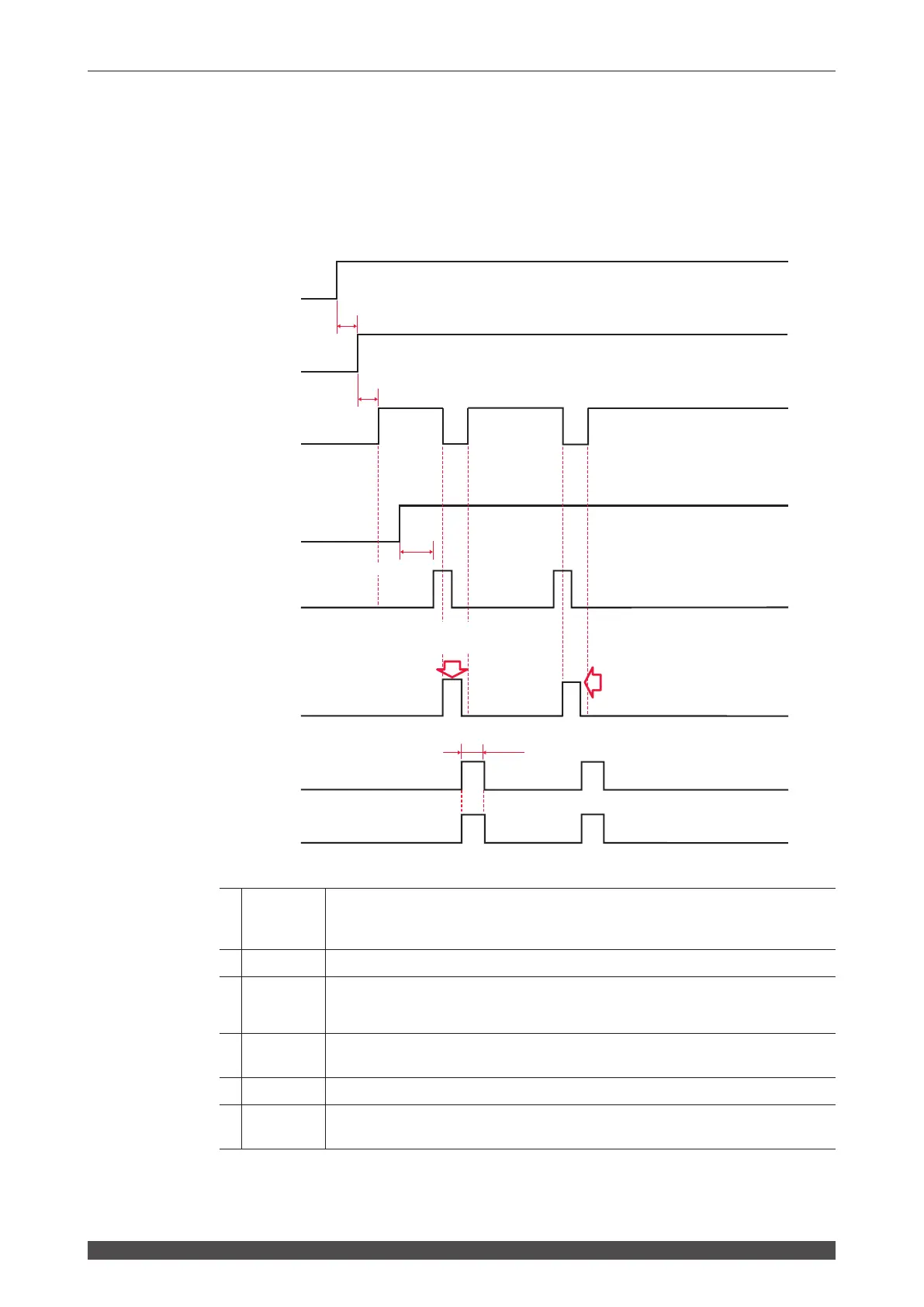
Timing Chart
Single ... Operation by laser controller (PANEL CONTROL)
The following diagram shows the lapse of time in the case where the "BEAM" setting
button is pressed and "SHUTTER" is set to ON on the laser controller, and then laser
light is output from branch unit 1.
*1
Output when the LD power supply is started. The laser is not turned ON. Repeat-
ing ON/OFF operation aects the lifetime of the electromagnetic contactor. Al-
ways turn this ON when in use.
*2 5s max. LD power supply start time
*3 1s max.
LD output preparation time. In the REPEAT mode, the signal is kept turned o
for certain time after laser output to keep the average power below the maximum
rated output. The signal is not output until a valid schedule is selected.
*4 150ms min.
Shutter operation time. After BEAM selection, a laser start input signal is input
after the lapse of certain time for shutter operation.
*5 Time required for the end signal to be output after a laser output
*6
Time required for outputting a signal to indicate whether the laser energy is within
the set upper limit value (HIGH) and lower limit value (LOW) of monitor output
In *5 and *6, the output time is 20 ms but can be changed to 30 or 40 ms on the CONFIG screen.
ON
OFF
ON
OFF
ON
OFF
ON
OFF
ON
OFF
150ms min. *4
Laser beam is projected from
Branch unit 1
*6
The time set on the CONFIG screen *5
Laser beam is projected from
Branch unit 1
LD PS ON/OFF Input *
LD PS Preparation
Output *1
Ready Output
Shutter Open Input *
Laser Start Input *
(Laser light)
End Output
Monitor Normal/
Trouble Output
(*: Operation on the user side)
5s max. *2
1s max. *3
 Loading...