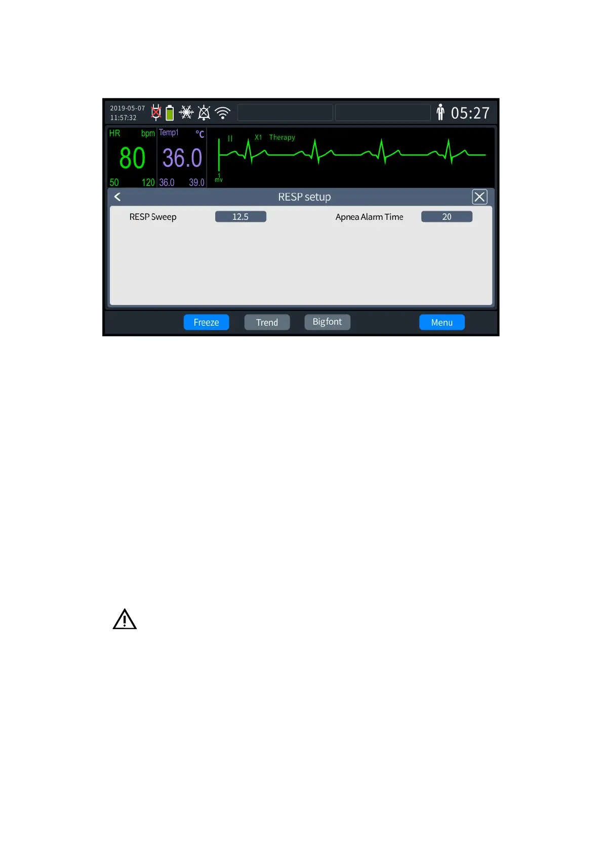
[RESP settings]. The RESP settings screen is shown in the following figure:
12- 2 RESP settings
2. Select [RESP Waveform Speed] to set the waveform speed to "6.25," "12.5" and "25".
3. Select [Apnea Alarm Time] to set the alarm time to "10," "15," "20," "25," "30," "35"
and "40".
4. Once set up, exit the settings screen, and the Defibrillator Monitor will automatically
update to the latest settings.
12.4 Place Respiratory Electrodes
Because the skin is a poor conductor, and to obtain a good respiratory signal, the skin where
the electrode is placed must be prepared. Refer to the ECG section for skin preparation.
Use standard ECG cable and electrode placement for respiration measurements. A different
ECG cable (3-lead or 5-lead) can be used. The respiratory signal is measured between two ECG
electrodes, which are RA (right arm) and LA (left arm) electrodes in lead I or RA (right arm) and LL
(left leg) electrodes in lead II, if the standard ECG electrode positions are used.
Caution:
To obtain the best respiration wave, RA and LA electrodes should be placed horizontally
when lead I is selected for respiration measurement. RA and LL electrodes should be placed
diagonally when choosing lead-II for respiration measurement. As shown in the figure below: