5
Table of Contents Operator Manual387366-389
LIST OF FIGURES
Description Page
Figure 3-1. Vented Closures .................................................................................................................................. 3-5
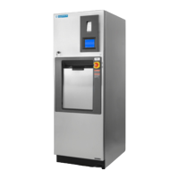
Figure 4-1. AMSCO 250LS Sterilizer ..................................................................................................................... 4-1
Figure 4-2. Main Power Disconnect Switch Location ............................................................................................. 4-2
Figure 4-3. Steam and Water Supply Valves ......................................................................................................... 4-2
Figure 4-4. Example of In-Cycle Touch Screen ..................................................................................................... 4-3
Figure 4-5. Printout ................................................................................................................................................ 4-4
Figure 4-6. Printout: Sterilizer Type ....................................................................................................................... 4-5
Figure 4-7. Printout: Alarm Condition..................................................................................................................... 4-5
Figure 4-8. Emergency Door Operation ............................................................................................................... 4-10
Figure 4-9. Optional Electric Steam Generator .................................................................................................... 4-13
Figure 5-1. Thermal Printer .................................................................................................................................. 5-12
Figure 5-2. Accessing Duplicate Print .................................................................................................................. 5-12
Figure 6-1. Check Chamber Drain Strainer............................................................................................................ 6-2
Figure 6-2. Steam and Water Supply Valves ......................................................................................................... 6-2
Figure 6-3. Slide Shelf Half Way Out of Chamber ................................................................................................. 6-3
Figure 6-4. Positioning Loaded Transfer Carriage (Typical) .................................................................................. 6-4
Figure 6-5. Ethernet Adapter Setup ..................................................................................................................... 6-91
Figure 6-6. Set IP and Subnet Mask .................................................................................................................... 6-91
Figure 8-1. Thermal Printer .................................................................................................................................... 8-2
Figure 8-2. Positioning Paper Roll ......................................................................................................................... 8-2
Figure 8-3. Take-Up Spool..................................................................................................................................... 8-3