UG-1828 Preliminary Technical Data
Rev. PrB | Page 146 of 277
GAIN CONTROL DETECTORS
In this section, three gain control detectors will be discussed in more details.
Analog Peak Detector (APD)
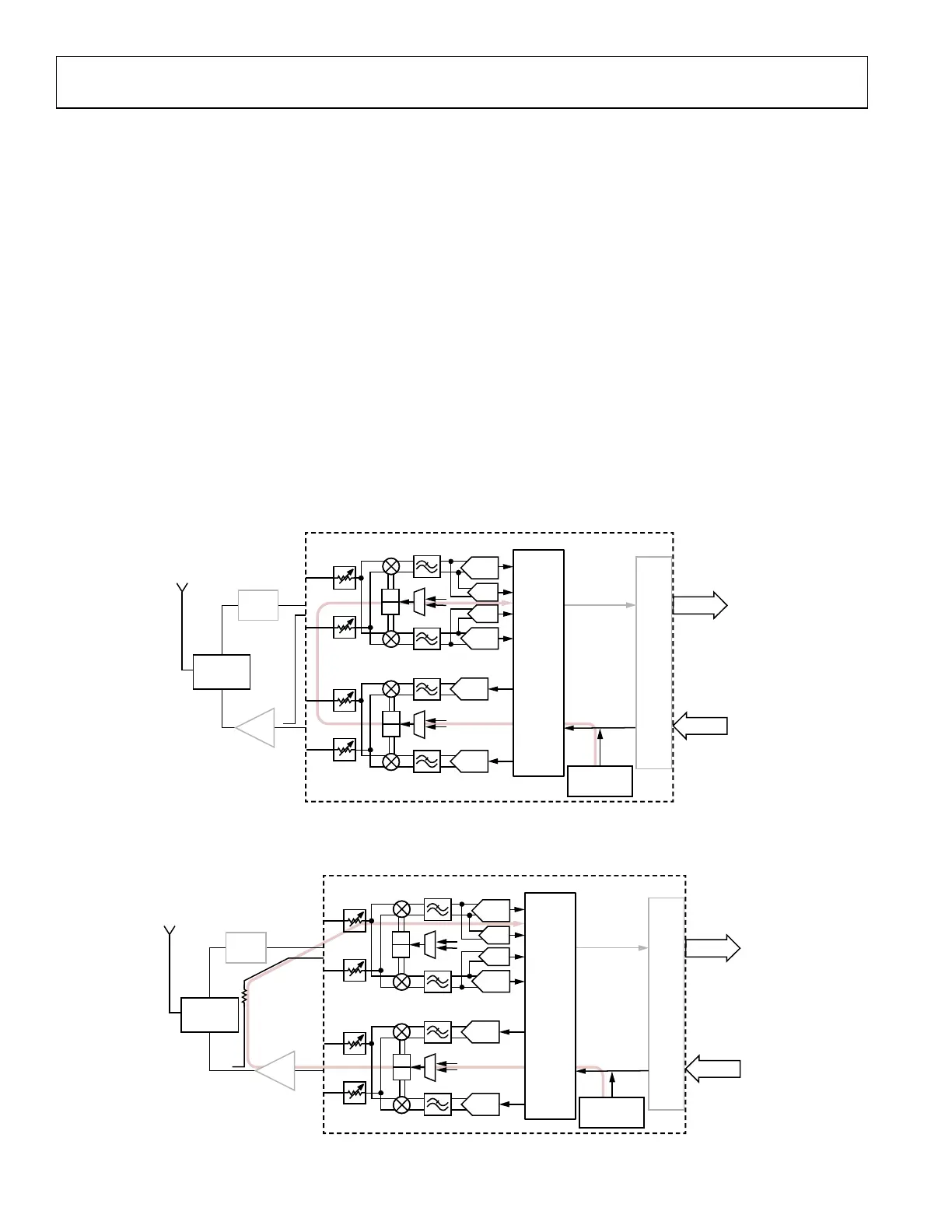
The analog peak detector is located in the analog domain following the TIA filter and prior to the ADC input (see Figure 105). It
functions by comparing the signal level to programmable thresholds. When a threshold has been exceeded a programmable number of
times in a gain update period, then the detector flags that the threshold has been overloaded.
apdLowThresh (mV)
apdHighThresh (mV)
t
24159-
114
Figure 141. Analog Peak Detector Thresholds
There are two APD thresholds as shown in Figure 140. These thresholds are contained in the agcPeak API structure, apdHighThresh and
apdLowThresh, respectively. The thresholds are typically considered relative to full scale voltage of the ADC, which is 850mVpeak. The mV
setting of the APD thresholds can be determined using the following equations:
To determine the setting of the APD thresholds in terms of the closest possible setting in terms of dBFS of the ADC assuming
apdHighdBFS and apdLowdBFS for apdHighThresh and apdLowThresh, respectively, the following equations can be used:
The APD threshold must be exceeded a programmable number of times within a gain update counter period before an over range
condition occurs. Both the upper and lower thresholds have a programmable counter in the API structure, as indicated in Table 62.
Table 62. APD Programmable Threshold Counters
Threshold Counter
Upper Threshold
(apdHighThresh)
apdUpperThreshPeakExceededCnt
Lower Threshold
(apdLowThresh)
apdLowerThreshPeakExceededCnt
As described in the earlier section on AGC control, the APD is used for both gain attack and gain recovery in peak detect mode. In
peak/power detect mode, the APD could be used for gain attack, and is used to prevent overloading during gain recovery. For more
details, refer to the relevant sections.
In AGC mode, the APD has programmable gain attack and gain recovery step sizes as shown in Table 63.
 Loading...