Preliminary Technical Data UG-1828
Rev. PrB | Page 37 of 277
ADRV9001 API initialization functions during the initialization phase. When programming is completed, the system is fully calibrated.
With a few additional API calls, the device is ready to operate.
The TES also provides the capability of generating a MATLAB code or python (.py) script or C code which includes all high level API
initialization calls after successfully programming the device. Those automatically generated codes or scripts can be given a file name and
stored in a location of the user’s choice for future use.
API INITIALIZATION SEQUENCE
As aforementioned, the initialization sequence is comprised of a serial of API calls intermixed with user-defined function calls specific to
the hardware platform. The API functions perform all the necessary tasks for device configuration, calibration and control. The
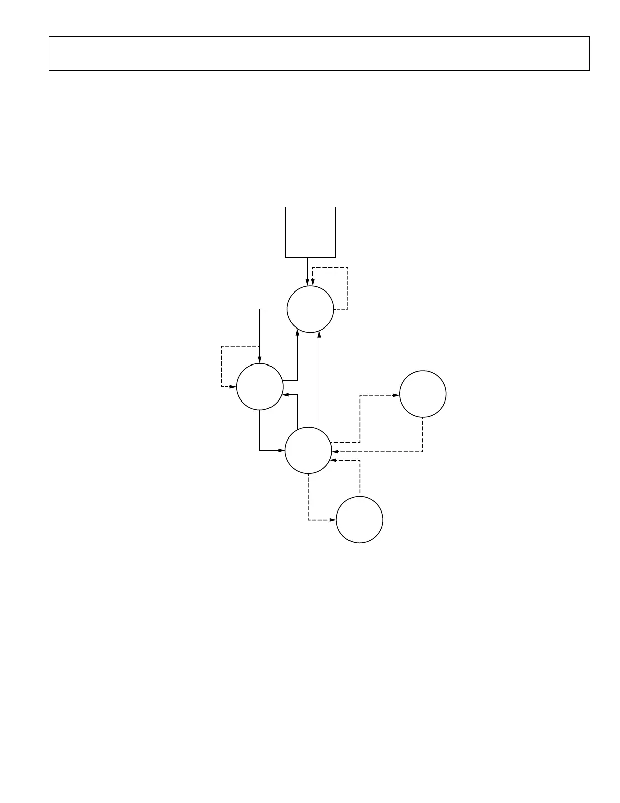
following diagram describes the state machine of the device from power up to RF enabled.
POWER_UP
STANDBY
STANDBY
STANDBY
CALIBRATED
CALIBRATE
ADDITIONAL
CALIBRATIONS
PRIMED
PRIME
UNPRIME
MONITORING
RF
ENABLED
CALIBRATE FAIL
AUTO
RF DISABLE
RF ENABLE
MONITOR
DISABLE
MONITOR
ENABLE
24159-018
Figure 17. Device State Machine
As shown in Figure 17, after power up, the device automatically enters the standby state, then the device initialization and calibration
begin. If it is successful, the device moves to the calibrated state, otherwise, it remains in standby state. Note when TES completes
programming, the device is in the calibrated state. After the device is calibrated, it must be further moved to the primed state, which
indicates that the device is ready for operation. Then, through SPI or PIN mode, the device can be moved to the RF enabled state by
enabling the transmit/receive channels so transmission and reception can start. Optionally, for power saving, the device can also enter
the monitoring state from the primed state. Refer to Power Saving and Monitor Mode section for details. In TES, after programming,
playing the receiver or transmitter moves the device from the calibrated state to the primed state and then to the RF enabled state.
This section mainly discusses the device initialization procedure from the standby state to the RF_ENABLED state. The related high level
API functions are discussed briefly in the following subsections. Refer to the doxygen document for details of each API function.
Note for MIMO systems with multiple inputs and outputs channels, multiple ADRV9001 devices might be involved. To synchronize
among all the devices, it requires a common device clock (DEV_CLOCK) and a multichip synchronization (MCS) signal so that all the
internally generated analog and digital clocks are aligned among all the devices. In addition, the MCS is used to synchronize the device
and baseband processor data interface for all devices. For simplicity, in the following descriptions, MCS operations are omitted from the
initialization steps. Refer to Clock Generation section in the user guide for more details.
 Loading...