Preliminary Technical Data UG-1828
Rev. PrB | Page 45 of 277
DATA INTERFACE
GENERAL DESCRIPTION
This document defines the synchronous serial interface (SSI) which transfer data between the ADRV9001 and a baseband processor .
ADRV9001 SSI consists of two receive channels and two transmit channels, the channels are independent and can be configured as
CMOS signals (CSSI) for applications that have narrow RF signal bandwidths and low data rate or as LVDS signals (LSSI) for
applications that require high speed, low noise and longer distance data transfer.
The CSSI supports below two modes of operation and can be operated as either in single data rate (SDR) or double data rate (DDR) data
transfer, the maximum clock frequency is 80 MHz.
• One lane data mode, I/Q data or other format data are serialized onto one single lane.
• Four lanes data mode, which is valid only when ADRV9001 transmit or receive I/Q samples and I/Q samples are 16 bits wide. In
four-lane data mode, each sample is split into 8 bits block of data and sent over one data lane.
The LSSI also supports two modes of operation, the LSSI always operates in DDR data transfer, the maximum clock frequency is up to
491.52 MHz.
• I/Q in one lane (one-lane mode)
• With I-Q data samples of 16 bits (total of 32 bits for each transfer)
• I/Q in separate lanes (two-lane mode)
• With I and Q data samples of 16bits
• With I and Q data samples of 12 bits
ADRV9001 SSI has various and flexible work modes to support all kinds of system scenarios, users can choose their appropriate work
modes according to the interface sample/symbol rate and bit width. Table 13 lists the ADRV9001 SSI work modes and the maximum
support I/Q sample rate.
Table 14. ADRV9001 SSI Work Modes
SSI Modes
Data Lanes Per
Channel
Serialization Factor Per
Data Lane
Maximum Data Lane
Rate (MHz)
Maximum Clock
Rate (MHz)
Maximum
Sample Rate
for I/Q (MHz)
Data
Type
CSSI 1-Lane 1 32 80 80 2.5 SDR
CSSI 1-Lane 1 32 160 80 5 DDR
CSSI 1-Lane
1
1 16/8/2 80-SDR/160-DDR 80 Not
Applicable
SDR/DDR
CSSI 4-Lane 4 8 80 80 10 SDR
CSSI 4-Lane 4 8 160 80 20 DDR
LSSI 1-Lane 1 32 983.04 491.52 30.72 DDR
LSSI 2-Lane 2 16 983.04 491.52 61.44 DDR
LSSI 2- Lane
2
2 12 737.28 368.64 61.44 DDR
1
ADRV9001 data port transmit/receive data symbols, refer CSSI Data Symbols Transmit and Receive.
2
For User’s LVDS data lane rate limitation applications, RX samples are rounded from 16 bits to 12 bits. Tx Sample are extended from 12bits to 16bits.
The following sections explain the details of the signals that make up the SSI and their properties when configured for each mode.
ELECTRICAL SPECIFICATION
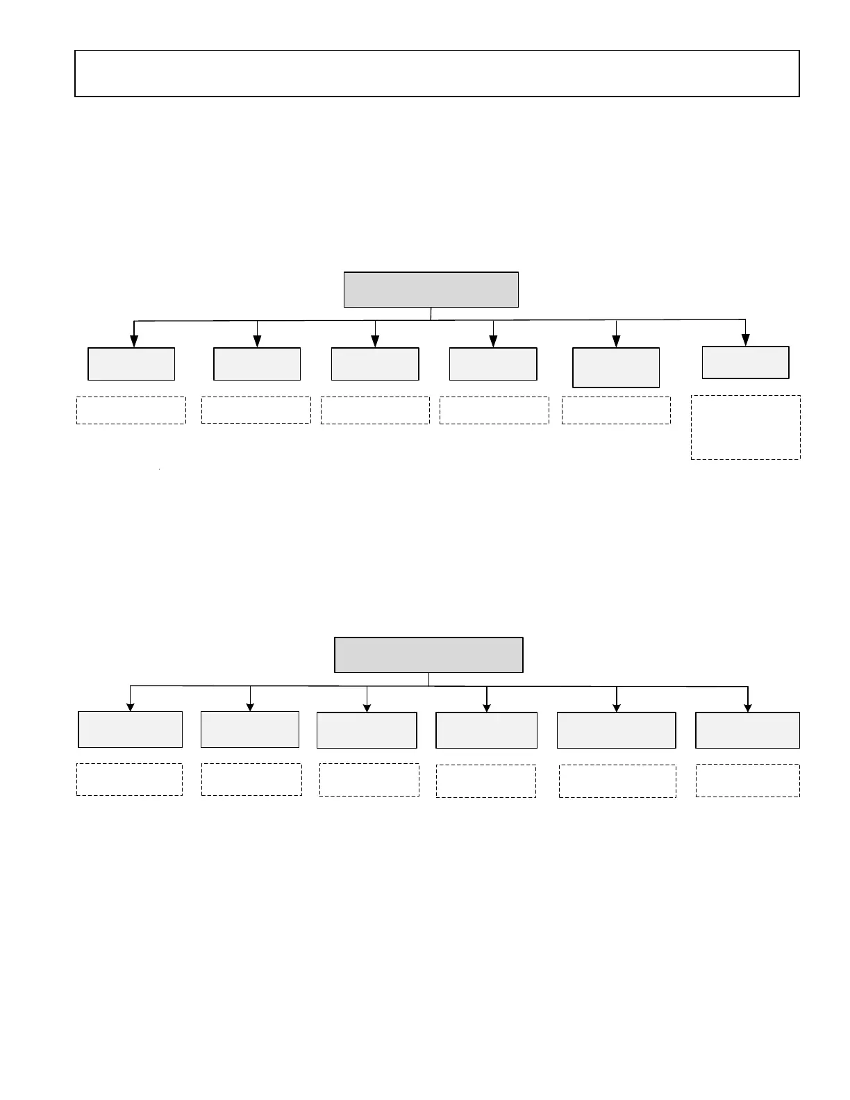
ADRV9001 SSI can operate in standard single ended CMOS compatible mode or Low-voltage Differential Signal (LVDS) compatible
mode, CMOS SSI and LVDS SSI share the IO pads of ADRV9001. Figure 24 describes the four channels with their corresponding IOs in
CMOS and LVDS modes.