UG-1828 Preliminary Technical Data
Rev. PrB | Page 80 of 277
1000
100
10
100 1000
ACHIEVABLE LO PHASE SYNC TIME (µs)
LO FREQUENCY (MHz)
24159-575
F
REF
= 400MHz
F
REF
= 350MHz
F
REF
= 360µs LINE
F
REF
= 300MHz
Figure 75. Theoretical Phase Sync Time up to 6GHz
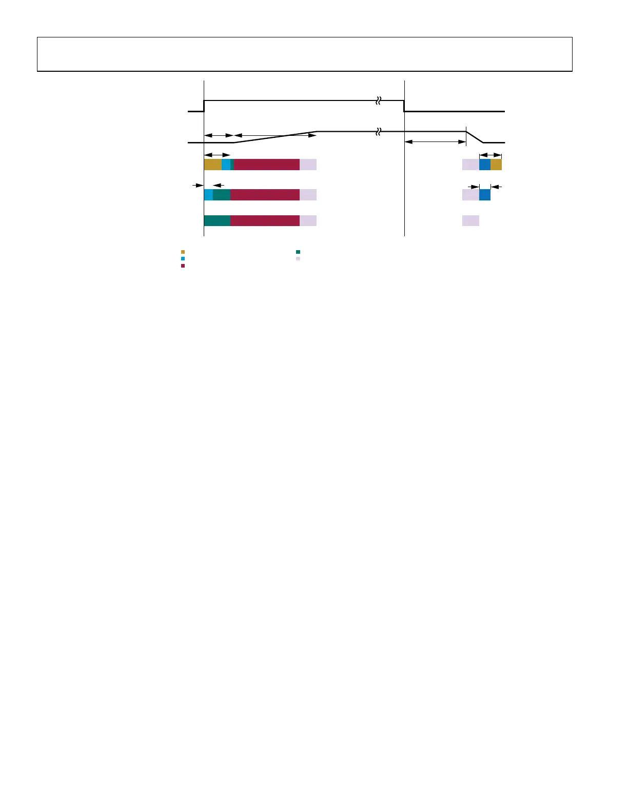
Figure 74 shows the phase synchronization timing when it is required. Note the higher the LO frequency and reference clock speed, the
lower the time it requires for phase synchronization. User should take this additional timing into consideration when designing
frequency hopping with phase synchronization.
Figure 75 shows the theoretical phase synchronization timing to up to 6 GHz. The actual time will vary but should be close to the
theoretical limit.
For frequency hopping, if user doesn’t want phase synchronization, then user can select MCS only mode. In this case user will not care
about phase synchronization time as it is not enabled. User will not have additional timing consideration because all MCS is done at the
initial stage not at the hop stage.
If user decides to have phase synchronized, then user should select MCS and phase sync mode. In this case user should take phase
synchronization as additional timing into account. As frequency hops the PLL phase will change and it will take the additional time to do
phase sync as mentioned above. This happens at the hop stage not at the initial stage.
MCS SUBSTATES (INTERNAL MCS STATE TRANSITION)
MCS Ready Substate
• Definition: ADRV9002 clock is switched from CLK PLL to Reference clock. MCS is initialized. Ready to receive MCS pulses.
• For current release 0.13, if the MCS command is sent with power saving mode > 0, ADRV9002 will return error
• All ADRV9002 chips can enter MCS Ready asynchronously. This means BBIC will wait for the ready status notified by all
ADRV9002 chips before issuing MCS pulses.
MCS Transition Substate
• Definition: ADRV9002 is in MCS pulse 1-6 transition but not finished.
• BBIC or clock chip sends MCS pulses to all ADRV9002 chips synchronously. BBIC monitors MCS status and restart MCS pulses if
needed to all ADRV9002 chips.
• Internally ADRV9002 keeps monitoring MCS status. After detecting the 5th MCS pulse, switch reference clock to clock PLL.
MCS Done Substate
• Definition: MCS procedure is done. ADRV9002 is ready to move to PRIMED state
• After received the 6th MCS, the substate is changed to MCS Done. ADRV9002 waits for toPrimed command or MCS command
again to re-run MCS.
• If MCS is not disabled, toCalibrated command would bring ADRV9002 back to MCS Done.
PROCEDURE
Before issuing MCS pulses, ADRV9002 needs to be in CALIBRATED state. BBIC can monitor MCS synchronization status by calling
adi_adrv9001_Mcs_Status_Get. After issuing one or all of the MCS pulses, this function can be used to check the synchronization status
of the analog and digital subsystems.
1. Entering MCS Ready substate
 Loading...