Section 4 Operation
4-86
(8) Open Loop Power Control Time Response measurement: Open
Loop Time Response screen
• The Open Loop Time Response screen appears by the following operation:
Step Key operation Description
1. [Main Func on off] F6 Sets the Main Func on to display the Main Menu at the bottom of the screen.
2. [TX&RX Tester] F1 Sets TX&RX Tester mode.
The Setup Common Parameter screen appears.
3. [TX Measure] F1 Displays the first page of the TX Measure menu.
4. Next Menu [ ] Displays the second page of the Main Func menu.
5. [Start] F5 Sets Call Processing state to Idle.
6. Connect call. Turn on the power of the mobile station under test.
Wait until the Call Processing state becomes Idle (Regist) after Registration.
7. [NW Originate] F2 Sets Call Processing state to Loop Back.
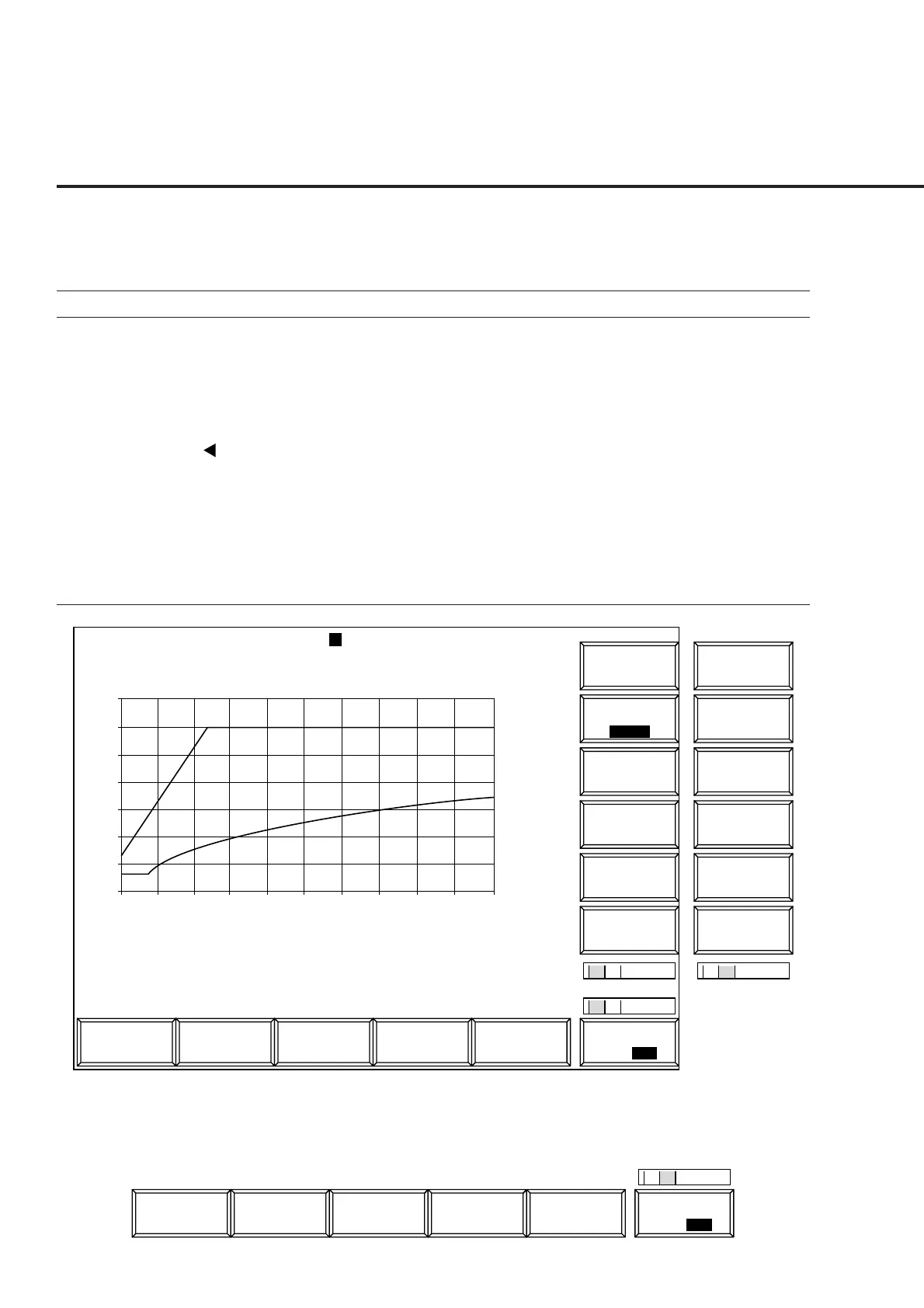
8. [Open Loop Power Cont] F10 Displays the Open Loop Time Response screen.
Initial TX Level : -13.7 dBm Marker : 33.6 ms
Current TX Level : -16.3 dBm 21.0 dB Pass
Setup Value : 1.0 dB
1
MT8801 99/12/31 12:00:00
<< Open Loop Time Response >>
Time Resp.
->
Back
Screen
Marker
BS Level
Step Up
Ready
Calibration
M
C
U
1
2
Channel : 0000CH Frequency : 1000.000 000MHz Level : -10dBm
BS Output
Level
Main Func
On Off
#
###
#
1
2
->
Back
Screen
Step Value
(dB)
30
25
20
15
10
5
0
-5
0 10 20 30 40 50 60 70 80 90 100
(ms)
Time Resp.
*
*
#
BS Level
Step Down
Start
1 2
Sync
Channel
Level
Paging
Channel
Level
Traffic
Channel
Level
Pilot
Channel
Level
Fig. 4-12 Open Loop Time Response Screen
The 2nd page of the main function keys on the Open Loop Time Response screen
1
Channel
Reference
Level
IF Level
Frame
Count
Main Func
On Off
#
##
2