Section 4 Operation
4-122
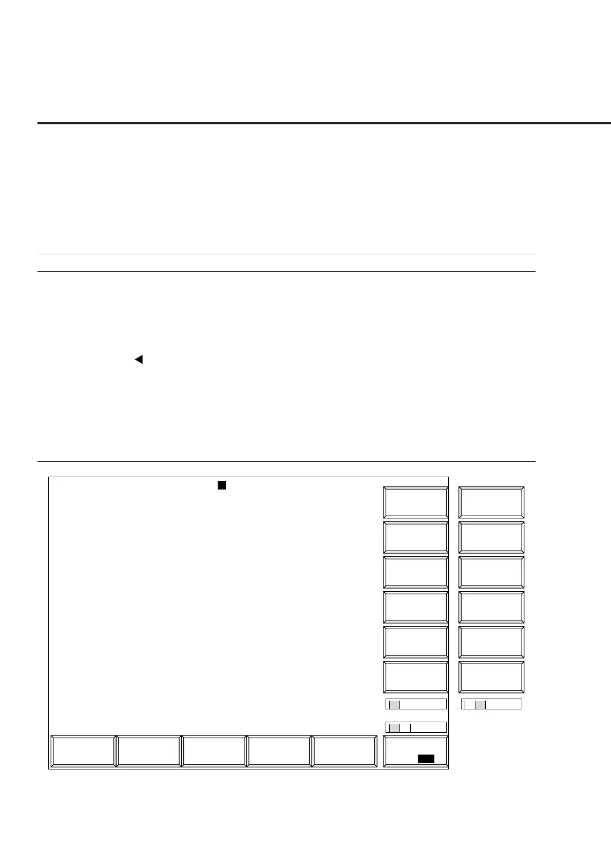
(3) Measuring the frame error rate (FER): Frame Error Rate screen
The following describes how to measure the frame error rate (on the Frame Error
Rate screen) of the receiver by using the parameters set on the Setup Common
Parameter, Setup RX Measure Parameter, and Setup Signal screens.
Some set items can be changed by using the function keys.
Displays the Frame Error screen according to the following steps to measure the
frame error rate.
Step Key operation Description
1. [Main Func on off] F6 Sets the Main Func on to display the Main Menu at the bottom of the screen.
2. [TX&RX Tester] F1 Sets TX&RX Tester mode.
The Setup Common Parameter screen appears.
3. [RX Measure] F2 Displays the first page of the RX Measure menu.
4. Next Menu [ ] Displays the second page of the Main Func menu.
5. [Start] F5 Sets Call Processing state to Idle.
6. Connect call. Turn on the power of the mobile station under test.
Wait until the Call Processing state becomes Idle (Regist) after Registration.
7. [NW Originate] F2 Sets Call Processing state to Loop Back.
8. [FER Measure] F7 Displays the Frame Error Rate screen.
1
MT8801 99/12/31 12:00:00
<< Frame Error Rate (CDMA) >>
FER Measure
->
Back
Screen
Sample
FER
Start/Stop
M
U
1
2
Channel : 0000CH Frequency : 1000.000 000MHz Level : -10dBm
BS Output
Level
Main Func
On Off
#
###
#
1
FER Measure
->
Back
Screen
BS Output
Level Cal.
FER Errors Transmitted / Sample Confidence Level
2.13% 8 375 / 2000 85.0%
Pass/Fail : Fail
-----------------------------------------------------------------
Confidence Level : 95.0 % Output Level
FER : 0.5 % BS Output Level : -100.0 dBm
FER Upper Limit : 0.6 % Pilot Level : -10.5 dB
Sync Level : -12.5 dB
Paging Level : -10.0 dB
Traffic Level : -12.0 dB
OCNS Level : -55.0 dB
AWGN Level : -1.0 dB : On
Abs. AWGN Level : -101.0 dBm
Traffic Channel Data Rate : 1/2
#
#
1 2
Sync
Channel
Level
Paging
Channel
Level
Traffic
Channel
Level
Pilot
Channel
Level
Fig. 4-23 Frame Error Rate Screen