Section 6 Peformance Tests
6-8
(4) Test procedures: Frequency/waveform quality
Step Procedure
1. Initialize the MT8801C and the signal generator.
2. Set the MT8801C as follows:
RF Input/Output: Main Set it on the Instrument Setup screen.
Using Specification: IS-95A Set it on the Setup Common Parameter screen.
CDMA Channel: 340 Ch Set it on the Setup Common Parameter screen.
3. Display the Modulation Analysis screen of MT8801C:
4. Set the signal generator as follows:
System: IS-95
Output Level: 0 dBm
Modulation: On
Simulation Link: Reverse
Filter: SPEC1
CH1 (Channel Assign): Traffic
CH2 to CH4: Off
5. Execute “Measure Single” after the “Adjust Range” execution of MT8801C
6. Read the measured value as shown in the table below, and check whether it is within the
specification value.
7. Change the settings as “Using Specification: J-STD-008” and “CDMA Channel: 600” and perform
the measurement as same as above to read the result.
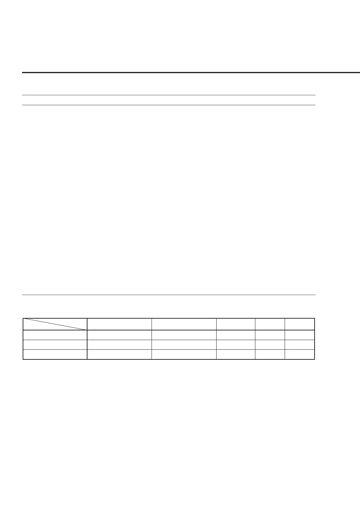
Frequency/waveform quality
Carrier frequency error
ρ (Waveform quality factor)
RMS vector error
340 CH (835.2 MHz)
__________ kHz
__________
__________ %
600 CH (1880 MHz)
__________ kHz
__________
__________ %
±0.1 Hz
< 0.008
2.5 %
+9.9 Hz
−−−−−−
5 %
−9.9 Hz
0.997
−−−−−−
Measurement
uncertainty
Effective
upper limit
Effective
lower limit