4-21
4.3 CDMA Transmitter and Receiver Test --- TX and RX Tester Mode
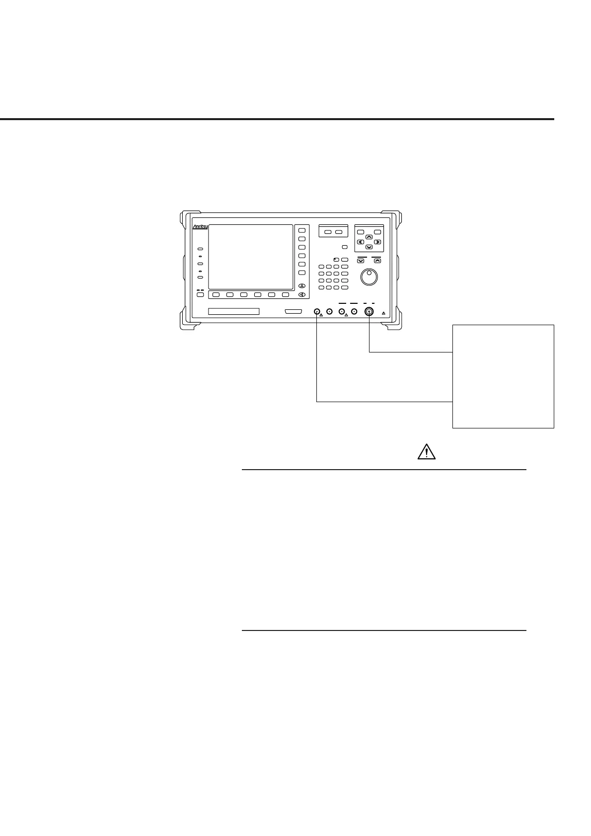
(c) Setup for Analog RX measurement
Send the modulated RF test signal from the MT8801C to the DUT which
demodulates the signal, input the demodulated result to the MT8801C,
then measure the distortion ratio.
RF IN
Divice under test
(receiver)
RF cable
SPEAKER
MT8801C front panel
MT8801C
Radio Communication
Analyzer
300kHz-3GHz
Input/Output
Main
Output
300kHz-3GHz
50‰
10W Max
20dBm Max
AUX
50‰
InputAF OutputAF InputDUT Interface
Stby
Copy
Panel Lock
Local
Remote
On
Preset
Set
Cancel
Single
Continuous
Step
Measure
Cursor
F 7
F 8
F 9
F 10
F 11
F 12
F 1 F 6F 5F 4F 3F 2
Next Menu
Hz
V
s
kHz
mV
ms
MHz
dB /V
sec
GHz
dBm
dB
0
. - / +
Enter
123
56
BS
4
89
Shift
7
D
CA
W
W
nW
mW
EF
B
30V Max
FDD
25 contacts
CAUTION
• The maximum input level of the AUX Input connector
The maximum input level of the AUX Input connector is
+20 dBm. If a signal whose level exceeds the specified
value is input, the internal circuit of the MT8801C may be
damaged.
• AUX Output connector
The AUX Output connector is the dedicated output con-
nector of the signal generator in the MT8801C. If a trans-
mitter signal is input in the AUX Output connector, the in-
ternal circuit may be damaged.