13
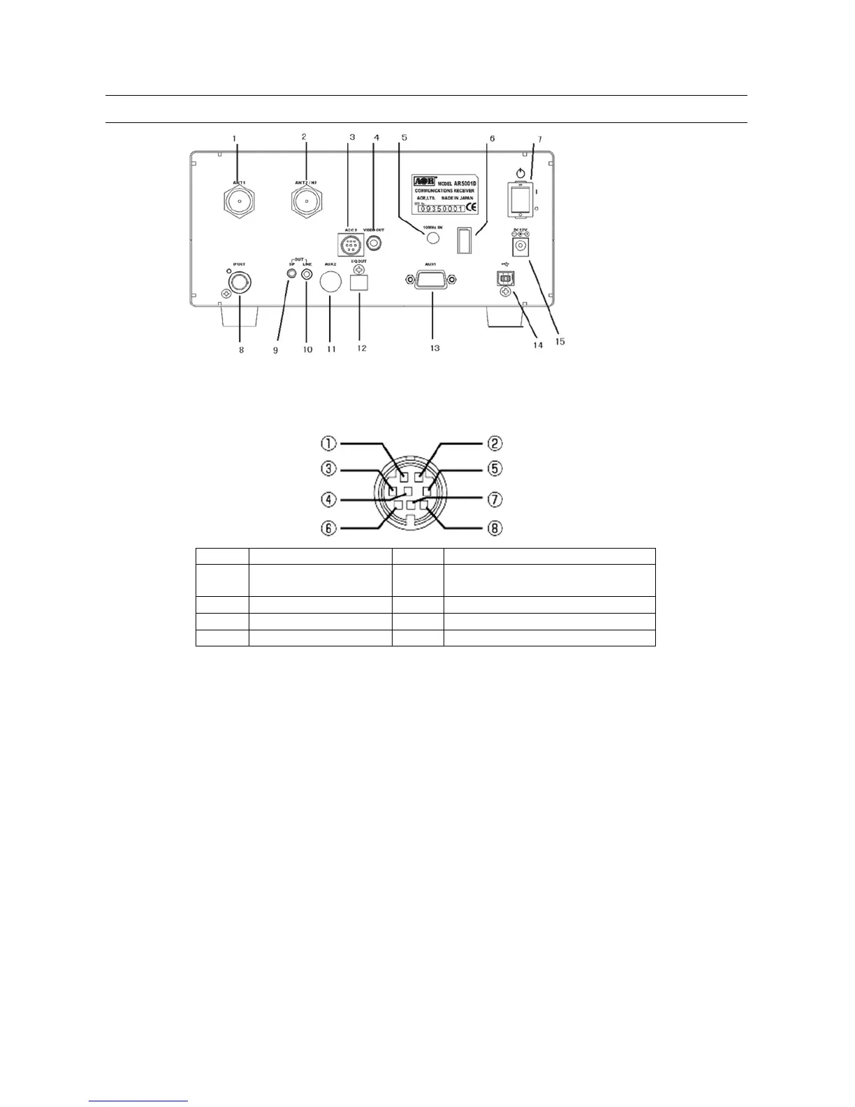
2-2 REAR PANEL
1. Antenna connector 1 (N type) (25MHz~3.15GHz)
2. Antenna connector 2 (N type) (40kHz~3.15GHz)
3. ACC2 (Accessory 2) connector
(50mA max.)
4. Composite video output (RCA type) 75 ohm 1V p-p
5. External 10 MHz reference signal input connector (SMA type) (2 dBm +/- 2dB)
6. Power cable clamp
7. Main power switch
8. 45.05 MHz IF output connector (BNC type)
(A 50 o hm terminator needs to be connected while no t in use.)
9. External speaker output (3.5 mm mono)
10. Line output connector (3.5 mm stereo, -10 dBm/600 ohm).
(Can be selected as 12 kHz I/Q output)
11. AUX2 (Auxiliary connector 2) Interface for an optional GPS unit
12. I/Q output connector (Optional, USB type B connector)
13. AUX1 (Auxiliary connector 1) D-Sub 9 Male, for expanded function (optional)
or RS-232C serial control interface
14. USB (2.0) connector (USB type B connector)
15. 12 VDC power input (2 A)