76
5. Press the [
MHz
] key to accept the entry and return to a standard display.
Alternatively, press the [
CLR
] key to abort entry, or press the [
DOWN
] key to move to the next item
on the configuration menu.
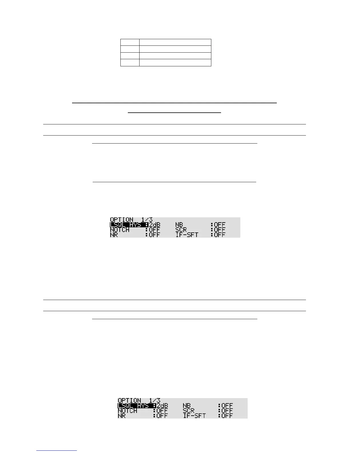
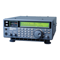
Note: On the spectrum scope screen, signals of only the selected frequency range
can be displayed while the filter is on.
10-12 VIDEO OUT (VIDEO OUTPUT)
Note: This function operates with a frequency of 25 MHz or higher.
The AR5001D has a built-in video decoder and composite video signal output is available from the video
output connector on the rear panel.
Note: Digital broadcast TV cannot be decoded with the AR5001D.
To activate the video o utput functio n, perform the follo wing steps:
1. Press the [
FUNC
] key, and then press the [
0
] key.
2. Press the [
DOWN
] key several times to select “VIDEO OUTPUT” in reverse contrast.
3. Rotate the sub dial to select on/off.
4. Press the [
MHz
] key to accept the entry and return to a standard display.
Alternatively, press the [
CLR
] key to abort entry, or press the [
DOWN
] key to move to the next item
on the configuration menu.
10-13 VIDEO IMG (VIDEO MODULATION POLARITY)
Note: This function operates with a frequency of 25 MHz or higher.
In some cases, certain FM video signals may be transmitted with an IF frequency revers ed, a nd
consequently, the received video signal cannot be properly decoded.
The AR5001D has a shift direction reverse function to correct the problem.
To activate the video modulation polarity func tion, perform the following steps:
1. Press the [
FUNC
] key, and then press the [
0
] key.