iPAM400 – Product Manual
U-0629-0171.doc – Issue: 04 complete, approved
Page 31 of 138
2. If fitted, then remove the iPAM400 front panel by undoing the two captive M3 Pozidriv screws on the
right side of the front panel.
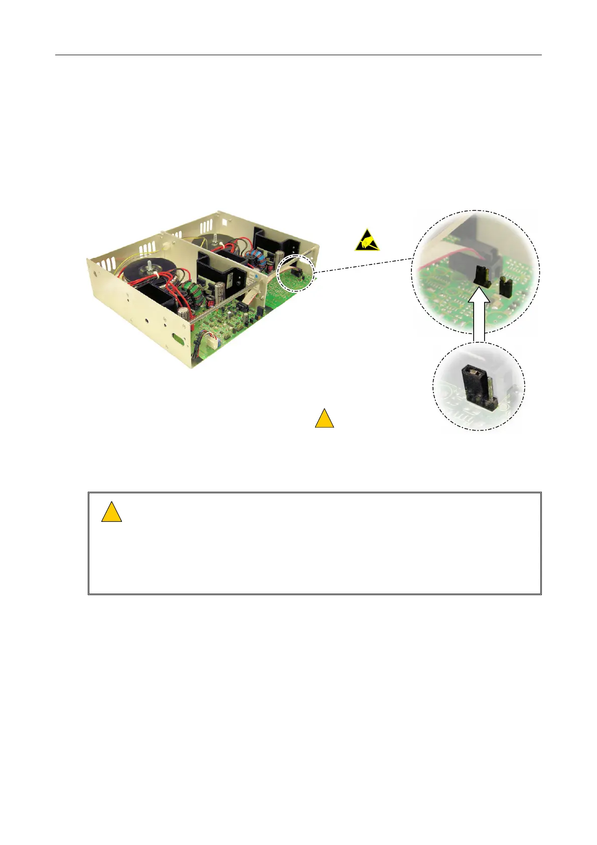
3. If a MX400 amplifier module is used and the loudspeaker line monitoring is performed using AC
surveillance with AEL01 or AEL02 Active End of Line Device, then the link setting on the amplifier
module needs to be adjusted as shown in Figure 7.
Please refer to the AEL01 or AEL02 user documentation for further details; see Table 7 (page 132).
Figure 7 MX400 link setting
!
!
DO NOT MAKE ANY
OTHER CHANGES!
LINK POSITIONED TOWARDS
THE TRANSFORM ON THE REAR
OF THE MODULE
4. Insert the chosen amplifier modules through the front of the mainframe, using the guides on the
inside top of the mainframe to locate them correctly; see Figure 8.
!
!
1) Ensure that the amplifier module’s side panels are located in the mainframe slides
on the inside top of the mainframe.
2) Ensure that the amplifier module is pushed fully home so that its rear connector(s)
mates the matching connector(s) in the mainframe.
3) Do not change any hardware settings on the amplifier module. These are set in
manufacture for optimum performance.