iPAM400 – Product Manual
U-0629-0171.doc – Issue: 04 complete, approved
Page 32 of 138
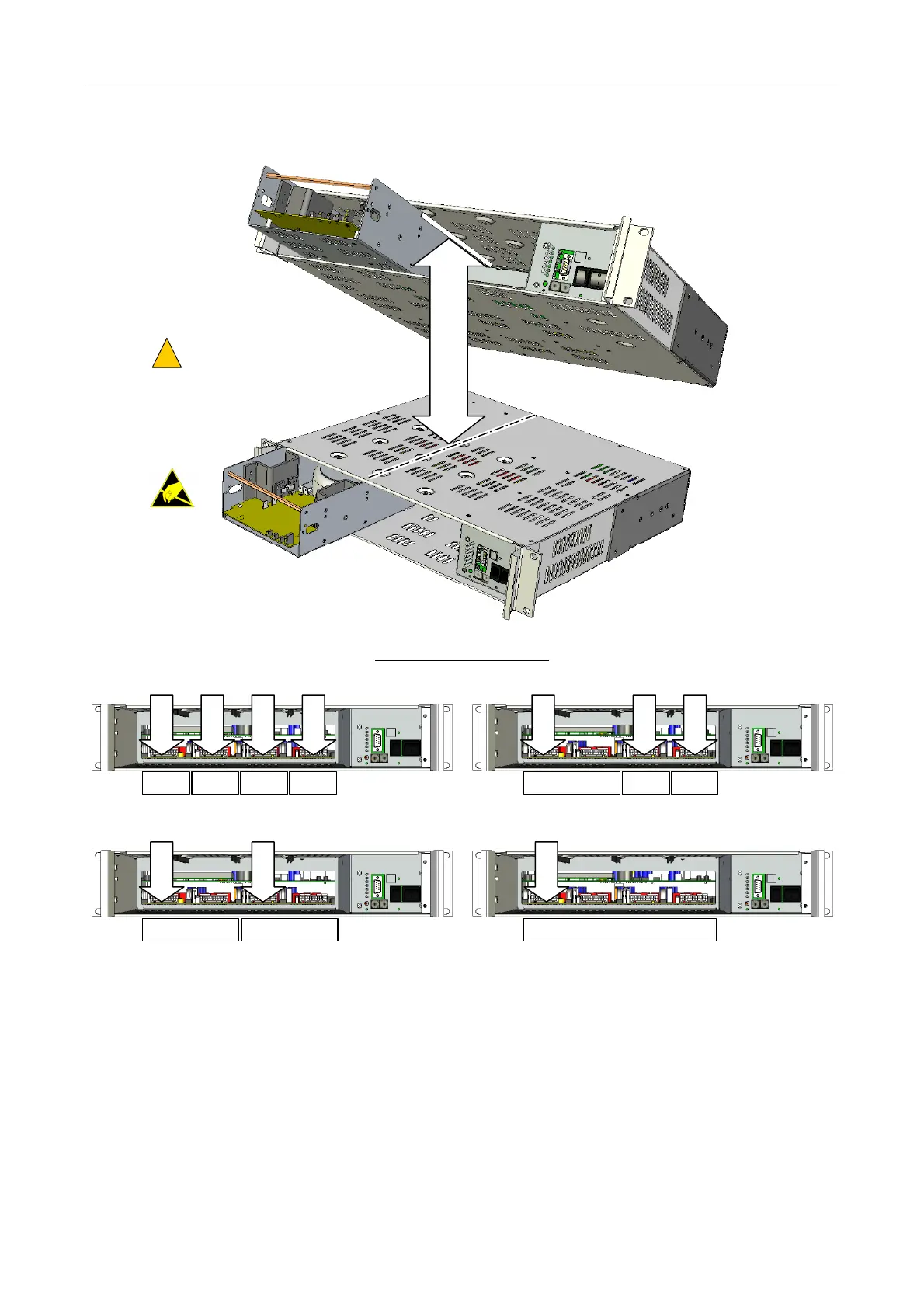
Figure 8 Installing the amplifier modules into the iPAM400
4 x MX100 CONFIGURATION
1
: 1 x 200 W + 2 x 100 W CONFIGURATION
1
:
MODULE SIDE PANELS MUST
LOCATE IN MAINFRAME SLIDES
!
!
(1 x MX200 shown as example.)
MX200
MX200
MAINFRAME SLIDE
MX100
SLOT 1
SLOT 2
SLOT 3
SLOT 4
MX100 MX100 MX100 MX200
SLOT 1
SLOT 3
SLOT 4
MX100 MX100
2 x MX200
CONFIGURATION
1
:
MX200
SLOT 1
SLOT 3
MX200
1 x MX400 CONFIGURATION:
MX400
SLOT 1
STANDARD CONFIGURATIONS:
1) The mainframe does not need to be fully populated with amplifiers, for example three MX100 amplifiers could be fitted, or a sin
le MX200