iPAM400 – Product Manual
U-0629-0171.doc – Issue: 04 complete, approved
Page 33 of 138
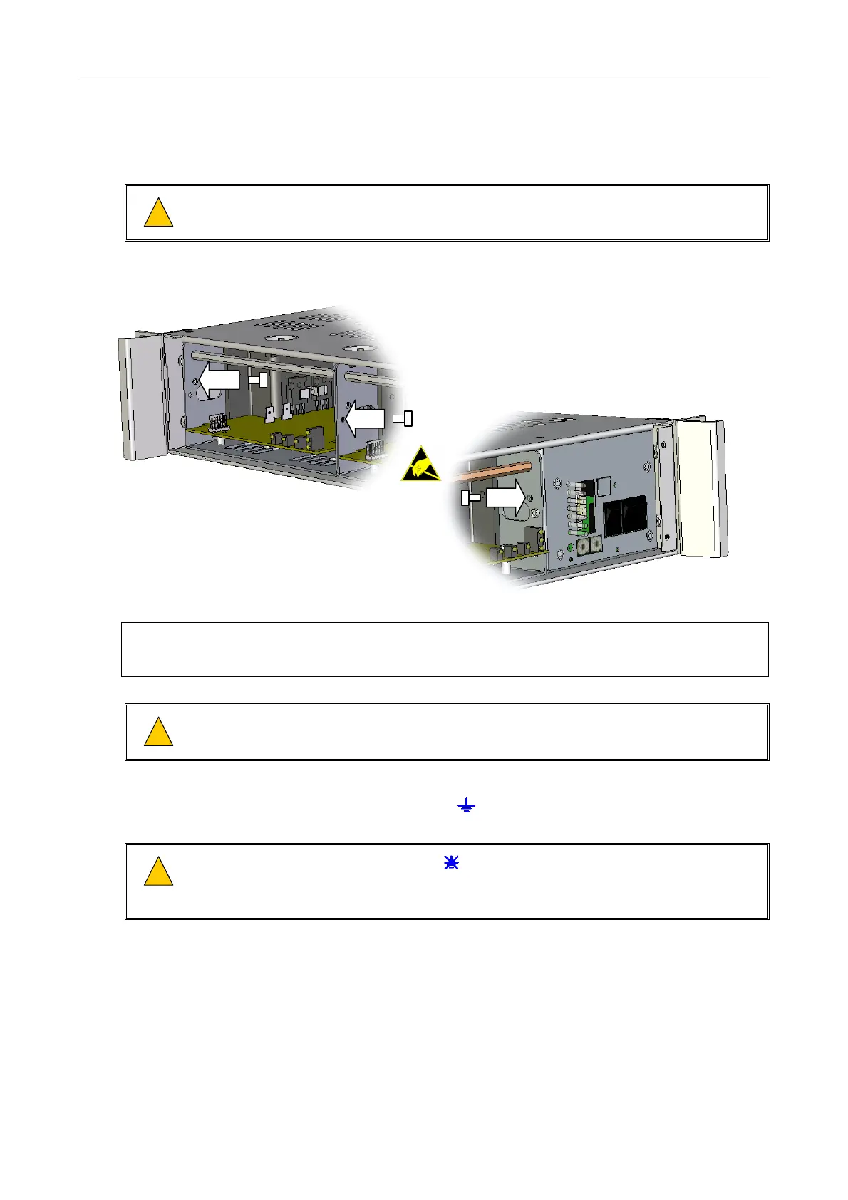
5. If the rack is to be transported, then secure the amplifier modules to each other and to the
mainframe sides using transit screws; see Figure 9.
!
!
Do not transport partially equipped mainframes. Either remove all amplifier modules,
or fix all modules in a fully populated mainframe using transit screws.
Figure 9 Fitting the transit screws
FIT THE M3 TRANSIT POZIDRIV SCREWS TO THE
LEFT HAND SIDE OF ALL AMPLIFIER MODULES AS
SHOWN ABOVE.
FIT THE RIGHT HAND M3 TRANSIT POZIDRIV
SCREW ON THE RIGHT-MOST AMPLIFIER
MODULE ONLY AS SHOWN BELOW.
The transit screws may be removed when the amplifiers are in situ to facilitate easy
removal of the modules.
!
!
The screws attaching the two parts of a MX400 amplifier module together should never
be removed.
6. Set the rear-panel EARTH LIFT switch to the DOWN ( , ON) ‘grounded’ position; see Figure 10.
!
!
Set the EARTH LIFT switch to the
UP ( , OFF) position to remove the mains earth from
the signal circuit if a +ve ground battery system is used, or it is necessary to avoid a
ground loop problem; see Section “5.4 Avoiding Ground Loop Problems” (page 58).
7. Set the rear panel DIP switches as required; see Figure 10.