iPAM400 – Product Manual
U-0629-0171.doc – Issue: 04 complete, approved
Page 35 of 138
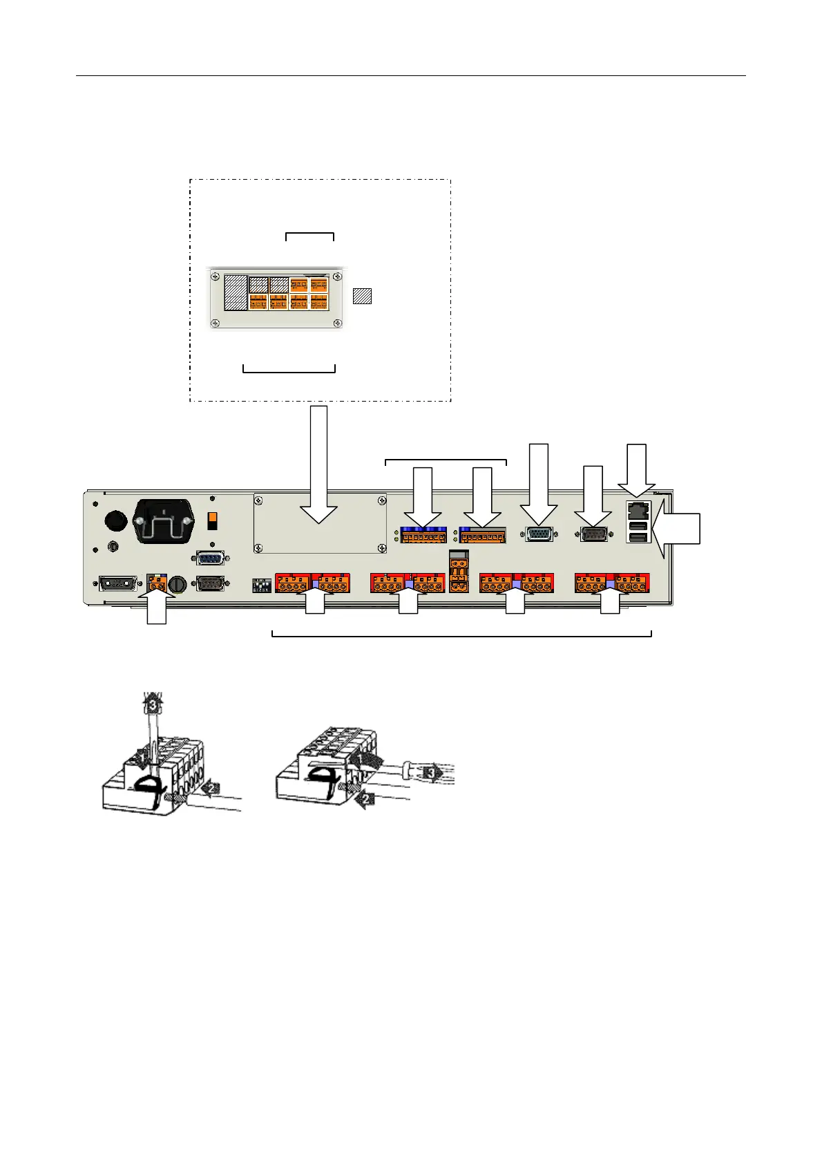
10. Connect the field wiring as required; see Figure 12.
Figure 12 Connecting the field wiring
Wago Connectors:
Use one of the two methods shown in the left
dia
ram to terminate the cablin
in the Wa
o
connectors.
When the screwdriver is removed, the bare end of
the wire will be held securely by the contact spring.
To remove the wire, reverse the process.
AUDIO I/O EXPANSION MODULE (OPTIONAL)
AUDIO IN/RS485 PORTS
VGA
RS232
ETHERNET
SLOT 4 SLOT 3 SLOT 2
SLOT 1
100 V OUTPUT LINES
1 2
USB
1
2
AUX DC OUTPUT
LOW LEVEL AUDIO OUTPUTS
OUT 1
OUT 2
OUT 3
OUT 4
AUDIO INPUTS
NOT USED
IN 3
IN 4
Please refer to Section “5.1 Terminal Allocation” (page 41) for pinout details.