Manual, Control and Signal Module, SA2 SA3
Document #9620-20-C-SA2 SA3-04
Pinnacle Park • 1031 Goodworth Drive • Apex, NC 27539 • Tel: 919.772.0115 • Fax: 919.772.8259 • www.ati-ia.com • Email: info@ati-ia.com
C-28
3rd ANGLE PROJECTION
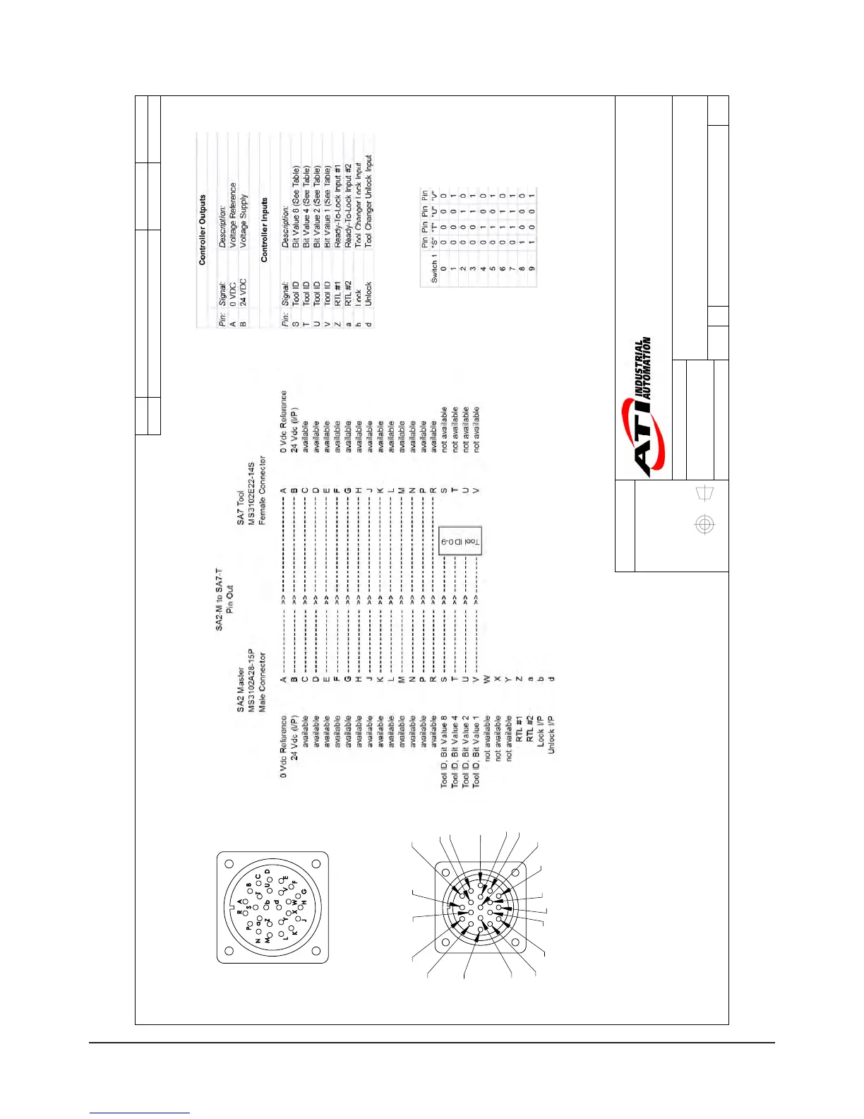
Amphenol Connector
Master Side
MS3102E28-12P
Face View
Scale 1:1
SA2 Master with SA7 Tool
M
A
B
C
D
E
F
G
H
J
K
L
N
P
R
S
T
U
V
Amphenol Connector
Tool Side
MS3102E22-14S
Face View
Scale 1:1
General Notes:
1. Pin A is first mate and last break during a tool change and is specified for use as
0 VDC and/or ground service.
2. The common for Tool ID is tied into the 0 VDC line (Pin A). The Tool ID switches are
Rated for service at 50V and 100 mA max. Refer to the Tool ID table for switch setup
information.
Rev.
Description
Initiator
Date
-
See Sheet1
- -
B
1:2
3 3
REVISION
NOTES: UNLESS OTHERWISE
SPECIFIED.
DO NOT SCALE DRAWING.
ALL DIMENSIONS ARE IN
MILLIMETERS.
DRAWN BY:
CHECKED BY:
C. Flesock, 5/7/07
R. Heavner, 5/7/07
TITLE
SCALE
SIZE
DRAWING NUMBER
PROJECT #
SHEET OF
9630-20-SA2M SA7T
02
PROPERTY OF ATI INDUSTRIAL AUTOMATION, INC. NOT TO BE REPRODUCED IN ANY
MANNER EXCEPT ON ORDER OR WITH PRIOR WRITTEN AUTHORIZATION OF ATI.
1031 Goodworth Drive, Apex, NC 27539, USA
Tel: +1.919.772.0115 Email: info@ati-ia.com
Fax: +1.919.772.8259 www.ati-ia.com
ISO 9001 Registered Company
SA2-M/SA7-T Customer Drawing