SmartROC D65 T4F 10 Options
160 No: 713944459.6 en
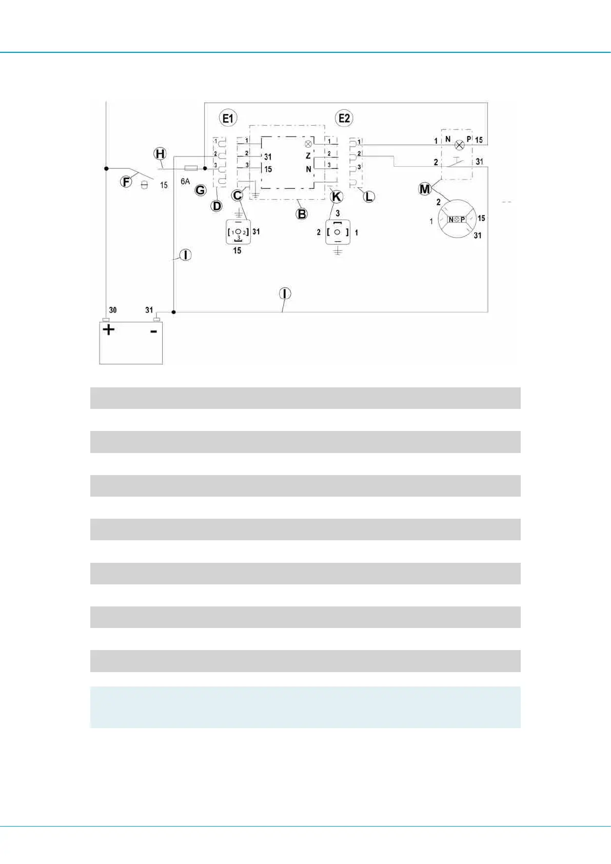
Circuit diagram
Fig. 16 - versions E1 and E2
A Timer
B Pump housing
C Terminal
D Cable contact
E1 Pump without extra push button
E2 Pump with extra push button
F Ignition lock
G Fuse
H Cable, black
I Cable, brown
K Terminal 2
L Cable contact
M Push button with lamp
!
NOTE: If pump model 103CS... E2 is replaced with pump model 203 CS...E2, the
cable to the lamp in the push button must be converted from negative to positive.

 Loading...