SmartROC D65 T4F 4 Daily checks
33 No: 713944459.6 en
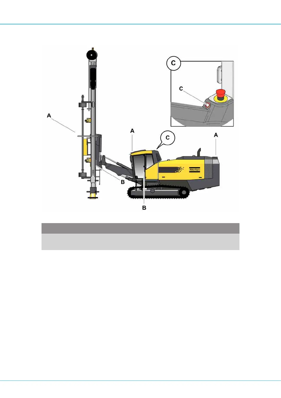
4.3.7 Electrical system
Electrical system
Check point Control object Action
A Work lights Front, rear and on feeder. Func-
tion
B, C Emergency stop buttons/Wire Attachment. Check each emer-
gency stop button individually.
The engine must stop. Before
you check the next emergency
stop button the previous button
must be reset before restarting.
There is an additional emer-
gency stop reset button in the
cabin (c) that must be de-
pressed in order to reset the
system. If the engine is hot,
there is a risk of damaging the
DEF injector by activating each
respective emergency stop but-
ton. In this case, the engine
must be restarted immediately
after each emergency stop but-
ton is depressed.
Table8: Electrical system
 Loading...