Disassembly and Replacement Procedures
DISASSEMBL
Y
AND REPLACEMENT
107
6-3. Main Body
6-3-1. Removing the Upper Section of the Main Body from the Main Body
(1) Remove the rear panel of the main body and pull
out the power box.
See (1) ~ (5) in “6-1-1. Removing the Main Body
from the HL Stand.”
(2) Remove the connectors and the ground wires from
the control board and the heater control board.
If the unit contains the SpO2 module, see (2) and (3)
in “6-4-1. Replacing the Control Board (for the Dual
Incu
i
)” and remove the slide plate.
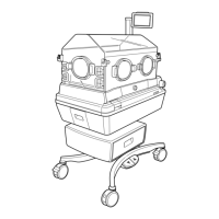
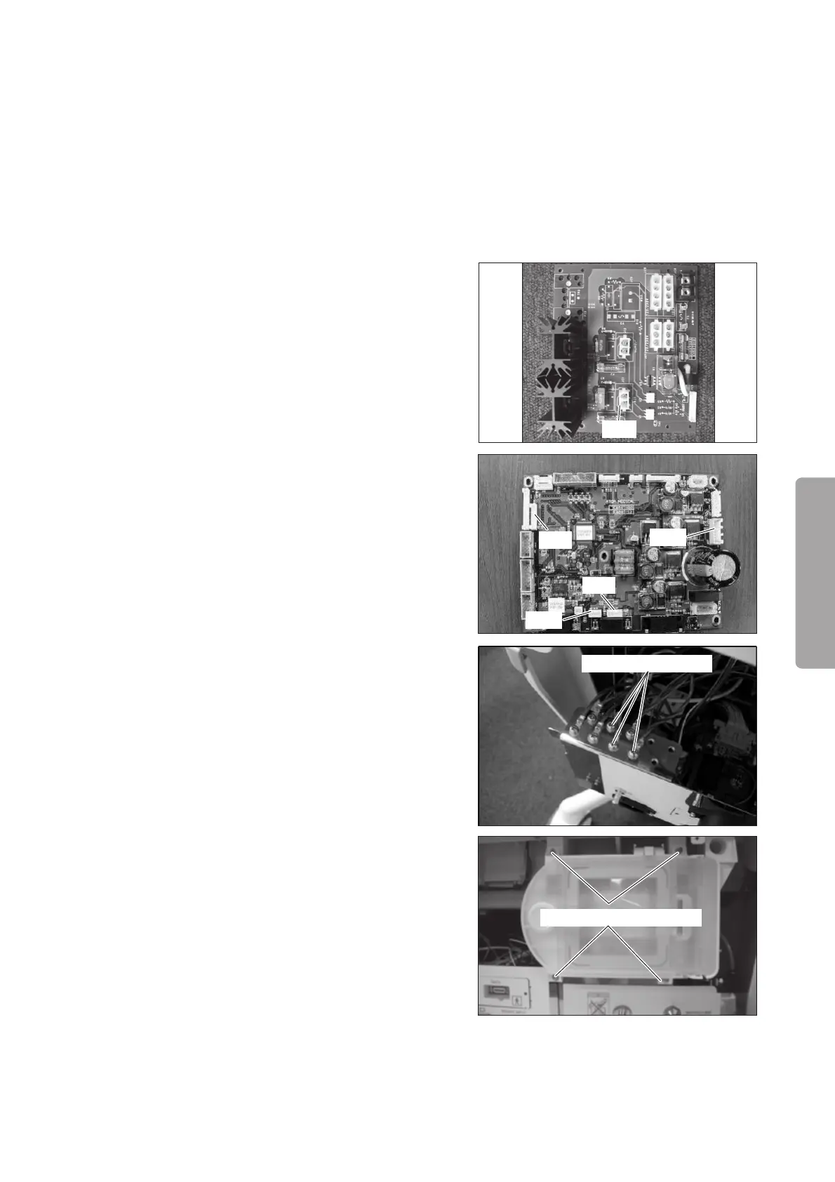
Remove the connector (JC1) from the heater con-
trol board (for the Incu i), and the connectors (JA5,
JA8, JA19 and JA21) from the control board (for the
Dual Incu i).
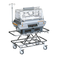
Remove the sems screws (M4 x 8) fixing the ground
terminals of the upper section of the main body, the
heater and the high temperature sensor with a
Phillips screwdriver.
For details, see the “[8] Wiring Diagram.”
If the unit contains the SpO2 module, see (2) and (3)
in “6-4-1. Replacing the Control Board (for the Dual
Incu
i
)” and remove the slide plate.
JC1
JA5
JA8
JA19
JA21
Sems screw (M4x8)
(3) Remove the filter assembly.
Remove the four double sems screws (M3 x 10) with
a Phillips screwdriver. Remove the pipe of the oxy-
gen supply valve and the connector of the position
detection board of the filter assembly.
Double sems screw (M3x10)