Disassembly and Replacement Procedures
DISASSEMBL
Y
AND REPLACEMENT
127
6-4-5. Replacing the Buzzer
(1) Pull out the power box and then remove the SpO2
unit and the SpO2 slide plate.
See (1) ~ (2) in “6-4-3. Replacing the Heater Con-
trol Board (for the Incu
i
).”
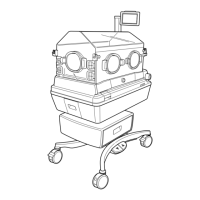
(2) Remove the connector connected to the control
board (for the Dual Incu i).
Remove the connector (JA17) from the control board
(for the Dual Incu i).
JA17
Sems screw (M3x8)
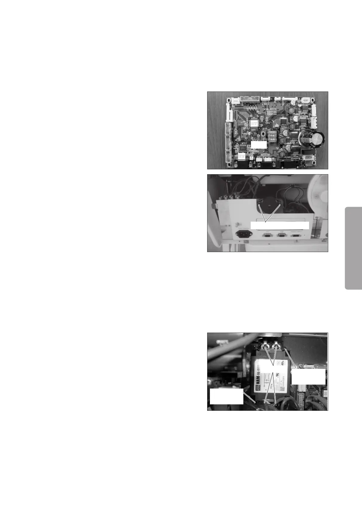
(3) Remove the buzzer from the power box.
Remove the two sems screws (M3 x 8) with a Phillips
screwdriver.
(4) Reassembly: Reassemble in the reverse order of dis-
assembly.
6-4-6. Replacing the Noise Filter
(1) Remove the power box. See (1) ~ (3) in “6-4-3. Re-
moving the Heater Control Board (for the Incu
i
).”
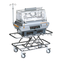
(2) Remove the noise filter.
Open the terminal base cover.
Remove the terminals fixing the terminal base with
a Phillips screwdriver.
Ter minal
Sems screws
(M4x8)
Sems screws
(M4x8)
(3) Reassembly: Reassemble in the reverse order of dis-
assembly.