Disassembly and Replacement Procedures
DISASSEMBL
Y
AND REPLACEMENT
119
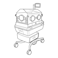
(3) Remove the control power transformer.
Remove the four tapping screws (M4 x 14) with a
Phillips screwdriver.
Tapping screw (M4x14)
Tapping screw (M4x14)
(4) Reassembly: Reassemble in the reverse order of dis-
assembly.
6-3-19. Replacing the Drive Power Transformer
(1) Remove the upper section of the main body from
the main body.
See (1) ~ (5) in “6-3-1. “Removing the Upper Sec-
tion of the Main Body from the Main Body.”
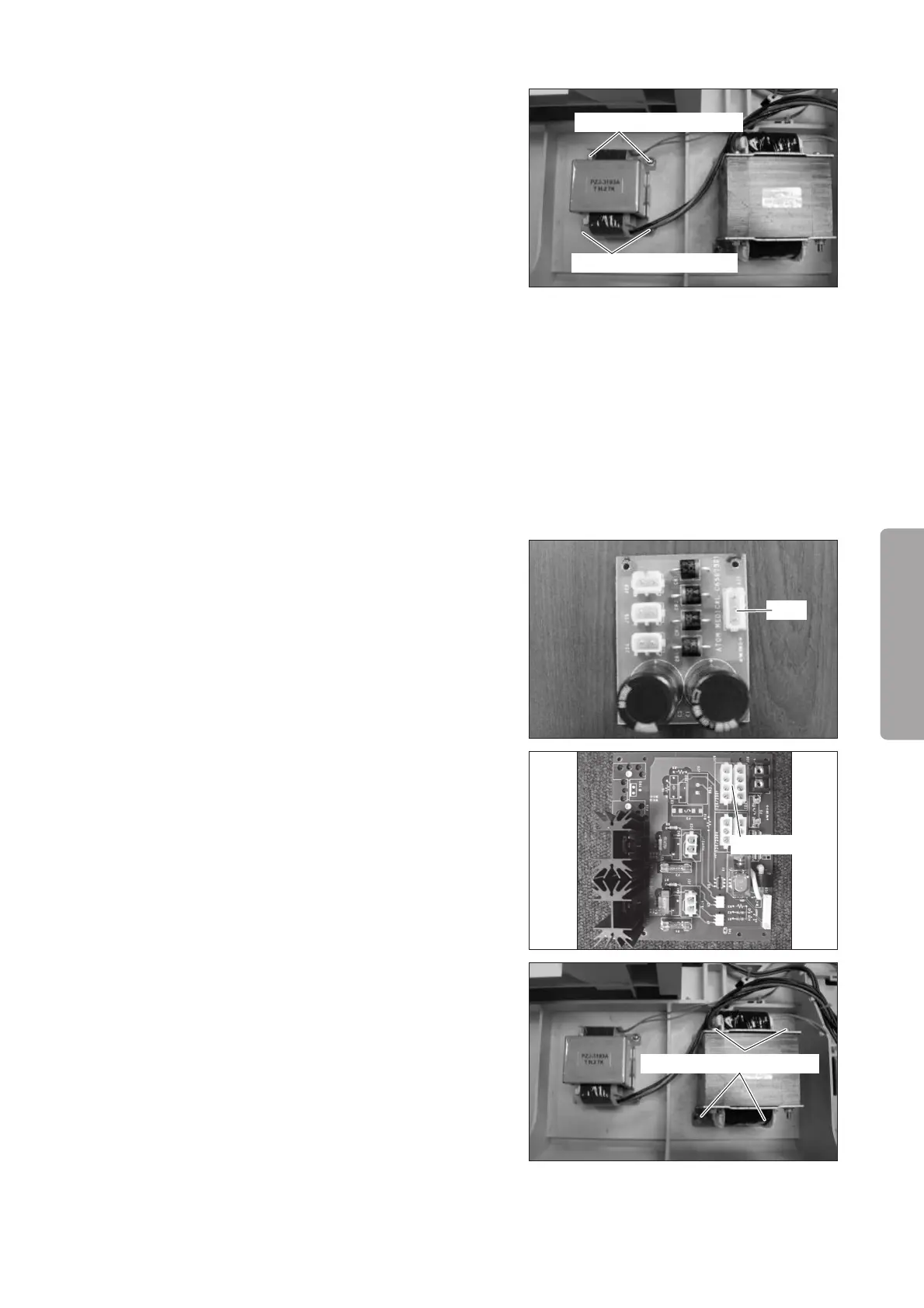
(2) Remove the wire.
Remove the connector (JI1) from the rectifier board
and the connector (JC8: 100V or JC9: 120V/230V)
from the heater control board (for the Incu i). Cut
the Tie Wrap fixing the removed wire.
For details, see “[8] Wiring Diagram.”
JI1
JC8 or JC9
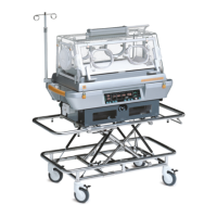
(3) Remove the drive power transformer.
Remove the four tapping screws (M414) with a
Phillips screwdriver.
Tapping screw (M4x14)
(4) Reassembly: Reassemble in the reverse order of dis-
assembly.