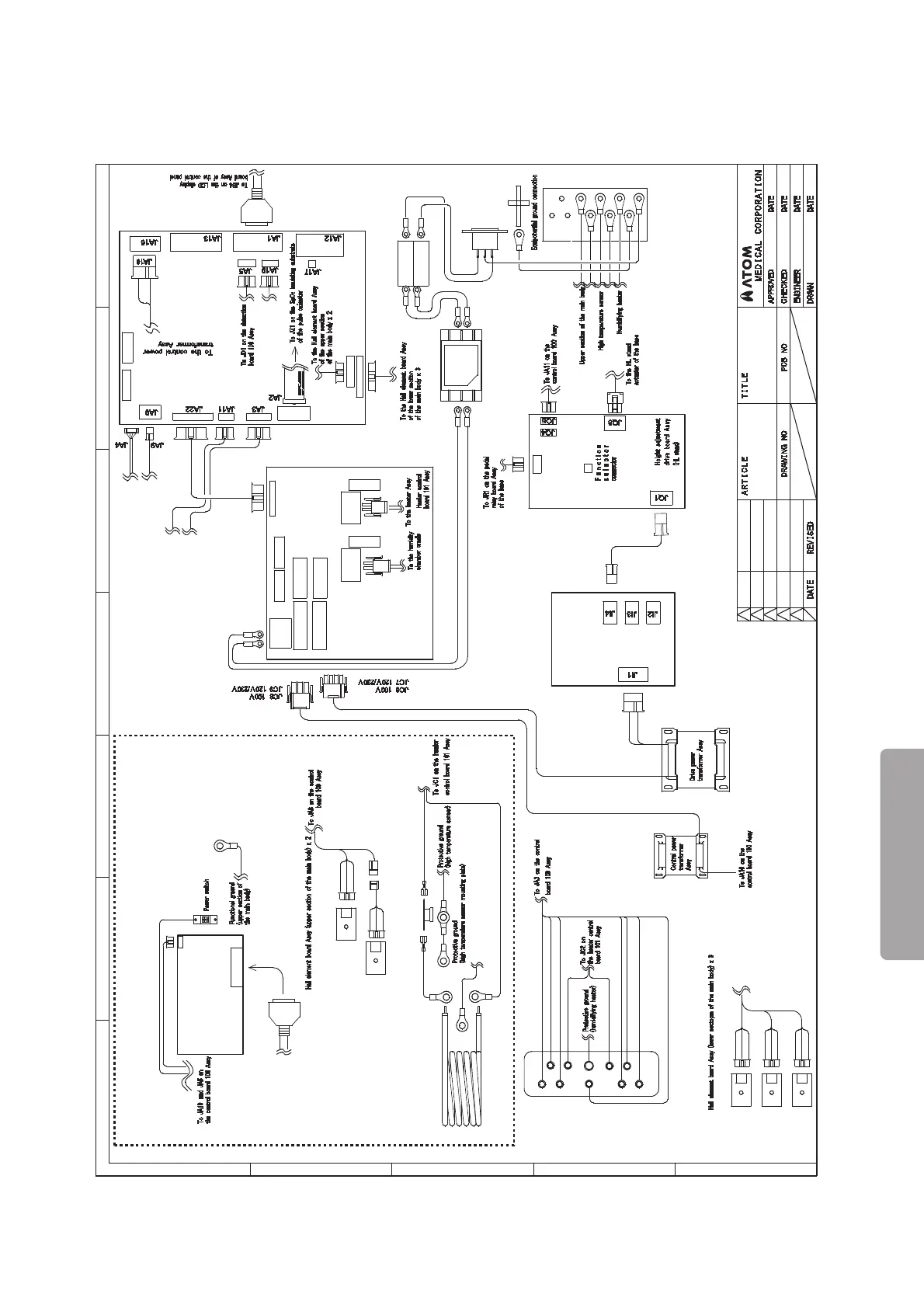
Wiring Diagram
INFORMATION
143
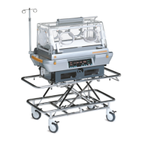
8-2. Main Body
E
D
C
B
A
54321
6 7
1997.6
Wiring Diagram
Incu i
(Main Body)
1
2
Yellow
Yellow
Orange
Orange
Brown
Brown
Brown
BrownBrown
JQ5
JQ8
JQ7
JQ10
S
Blue
Blue
Blue
JA10
JA8
Blue
Blue
F1F2
F5 F4
JC6
JC5
JC7
JC8
JC4
JC4
1
JC9
JC1JC2
N
L
Blue
Brown
Power cord inlet
Noise filter
Rectifier board Assy
Ground connection
Heater Assy
Protective ground (heater)
High temperature sensor Assy
Heater
Humidity chamber cradle
To the humidity chamber cradle
To the power switch
Detection board 100 Assy
JD1
JD5
To JJ3 on
the sensor module
Upper section
of the main body
To the solenoid valve Assy
To the mass flow valve Assy
of the oxygen controller
To JQ5 on the height adjustment
drive board Assy (HL stand)
Control board 10 0Assy
Humidity chamber cover detection sensor
Boiler cap detection sensor
Green
Gray
Brown
Filter cover detection sensor
To JA10 on
the contro lboard
100 Assy
Oxygen controller
Middle board detection sensor
Fan attachment detection sensor
Blue
Orange
JA21
JA4
Fuse holder
Incubator
Incu i
Purple