Disassembly and Replacement Procedures
DISASSEMBL
Y
AND REPLACEMENT
113
6-3-8. Replacing the Tilting Unit
(1) Remove the control box cover.
See (1) ~ (3) in “6-3-5. Replacing the Control Box
Cover.”
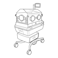
(2) Remove the tilting arm.
Remove the two setscrews (M6) with a hexagon
wrench (distance between the opposite sides: 3mm).
Move the V ring toward the tilting unit.
Setscrew (M6)
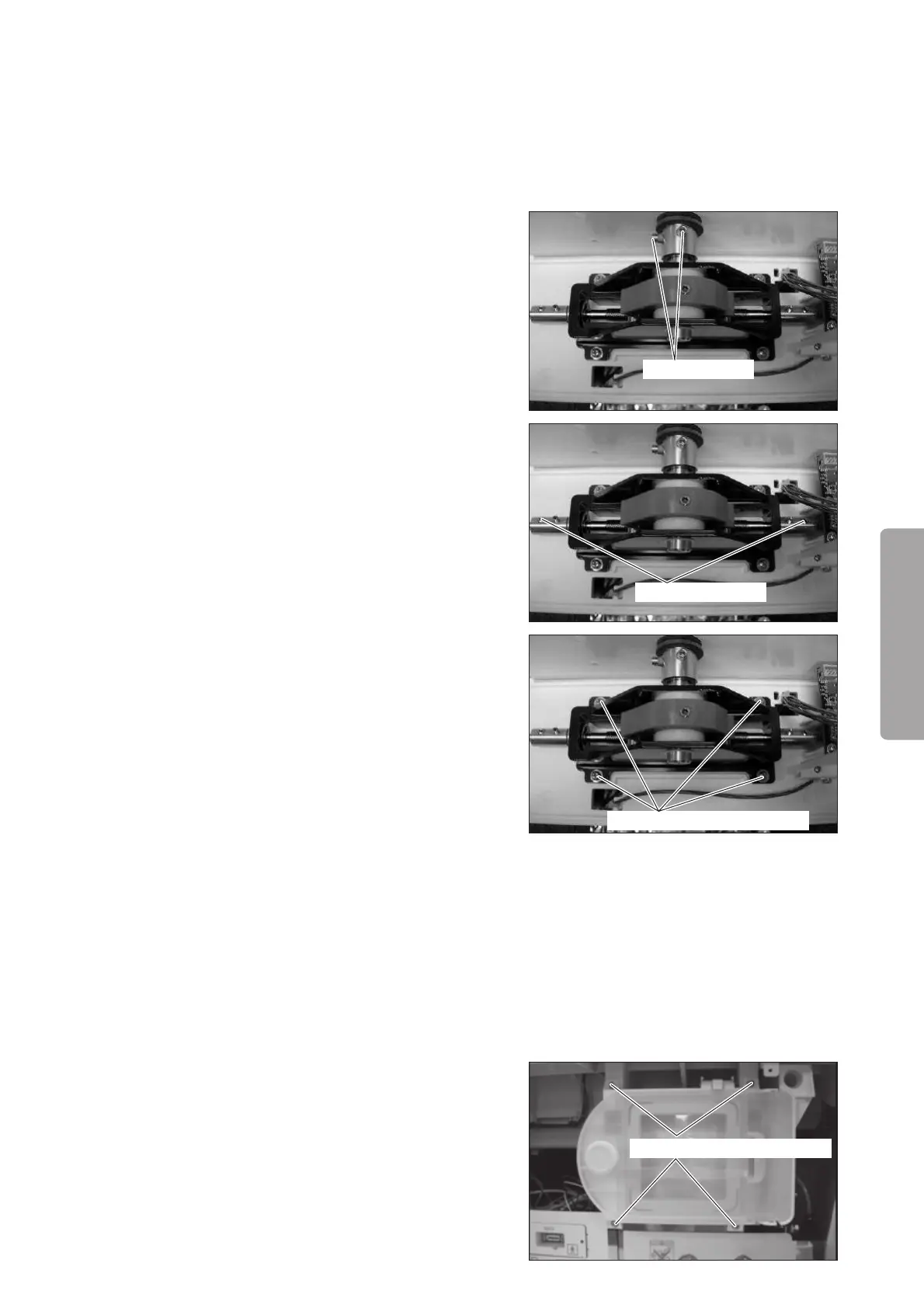
Setscrew (M5x10)
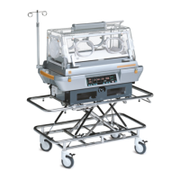
Double sems screw (M4x10)
(3) Remove the tilting knob.
Remove the two setscrews (M5 x 10) with a hexa-
gon wrench (distance between the opposite sides:
2.5mm).
(4) Remove the tilting unit.
Remove the four double sems screws (M4 x 10) with
a Phillips screwdriver.
(5) Reassembly: Reassemble in the reverse order of dis-
assembly.
6-3-9.
Replacing the Position Detection Board (for the Detection of the Middle Board)
(1) Remove the rear panel of the main body.
See (1) ~ (3) in “6-1-1. Removing the Main Body
from the HL Stand.”
(2) Remove the filter assembly.
Remove the four double sems screws (M3 x 10) with
a Phillips screwdriver.
Remove the pipe of the oxygen supply valve and the
connector of the position detection board of the fil-
ter assembly.
Double sems screw (M3x10)