Disassembly and Replacement Procedures
DISASSEMBL
Y
AND REPLACEMENT
97
6-1-2. Replacing the Actuator
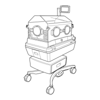
(1) Remove the main body from the HL stand.
See (1) ~ (8) in “6-1-1. Removing the Main Body
from the HL Stand.”
(2) Remove the HL stand table.
Remove the cable from the connector on the upper
part of the actuator and then remove the cable clamp
fixed with a screw.
Remove the four TORX screws (ø8 x 80) with a
TORX driver.
For details, see “[8] Wiring diagram.”
TORX screws (φ8x80)
(3) Remove the cover of the height adjustment actua-
tor.
Cover of the height adjustment actuator
(4) Remove the actuator from the HL stand base.
Remove the four TORX screws (ø8 x 80) with a
TORX driver.
TORX screws (φ8x80)
TORX screws (φ8x80)
(5) Reassembly: Reassemble in the reverse order of dis-
assembly.
6-1-3. Replacing the Foot Switch
(1) Remove the main body from the HL stand.
See (1) ~ (8) in “6-1-1. Removing the Main Body
from the HL Stand.”
(2) Lay the HL stand on its side.
Stand