Disassembly and Replacement Procedures
DISASSEMBL
Y
AND REPLACEMENT
111
6-3-5. Replacing the Control Box Cover
(1) Remove the rear panel of the main body.
See (1) ~ (3) in “6-1-1. Removing the Main Body
from the HL Stand.”
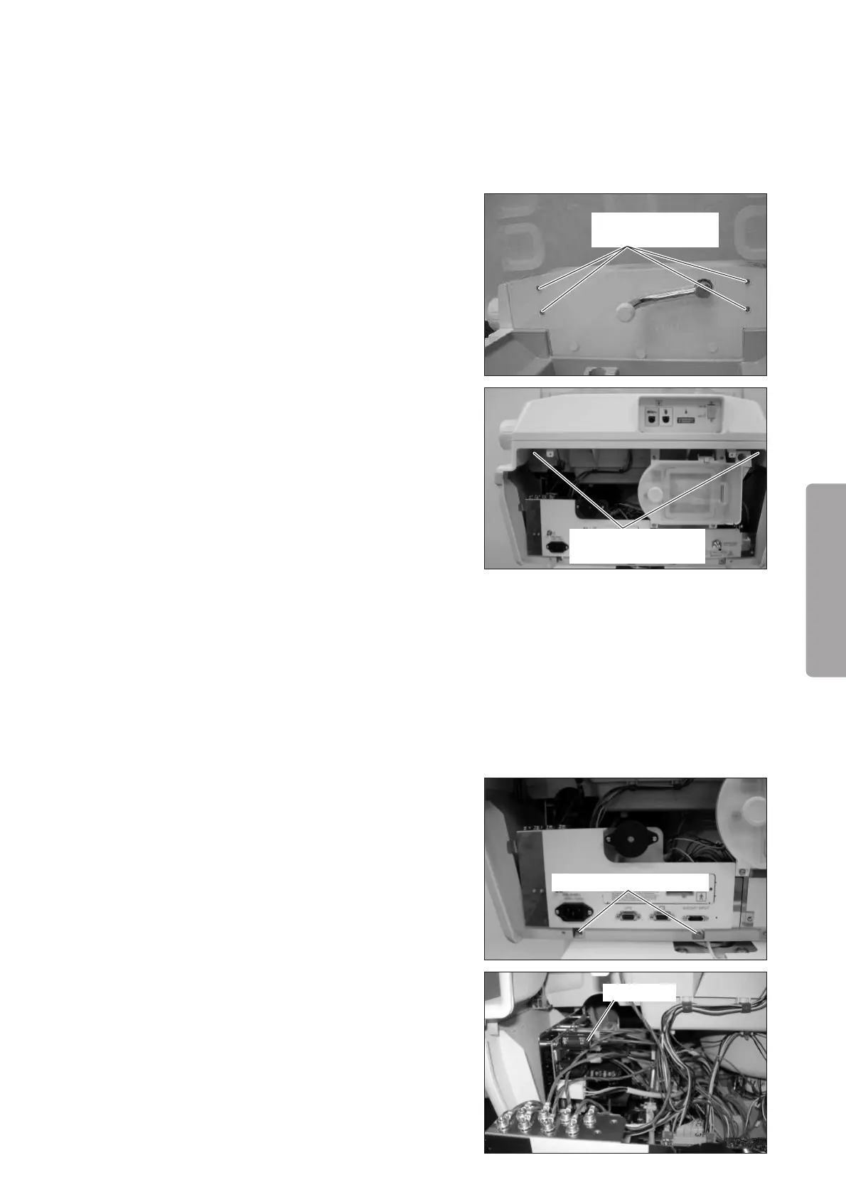
(2) Remove the control box cover from the hood.
Remove the four flat head machine screws (M4 x
12) from the hood with a Phillips screwdriver.
Flat head machine
screw (M4x12)
(3) Remove the control box cover from the upper sec-
tion of the main body.
Remove the two double sems screws (M3 x 10) from
the upper section of the main body with a Phillips
screwdriver.
Double sems screw
(M3x10)
(4) Reassembly: Reassemble in the reverse order of dis-
assembly.
6-3-6. Replacing the Power Switch
(1) Remove the control box cover.
See (1) ~ (3) in “6-3-5. Replacing the Control Box
Cover.”
(2) Pull out the power box.
Remove the two double sems screws (M3 x 8) fix-
ing the power box with a Phillips screwdriver.
Double sems screw (M3x8)
Power box