Disassembly and Replacement Procedures
112
(3) Remove the connector from the control board (for
the Dual Incu i).
If the unit contains the SpO2 module, see (2) and (3)
in “6-4-1. Replacing the Control Board (for the Dual
Incu
i
).”
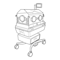
Remove the connector (JA19) from the control board
(for the Dual Incu i ).
For details, see “[8] Wiring Diagram.”
Connector (JA19)
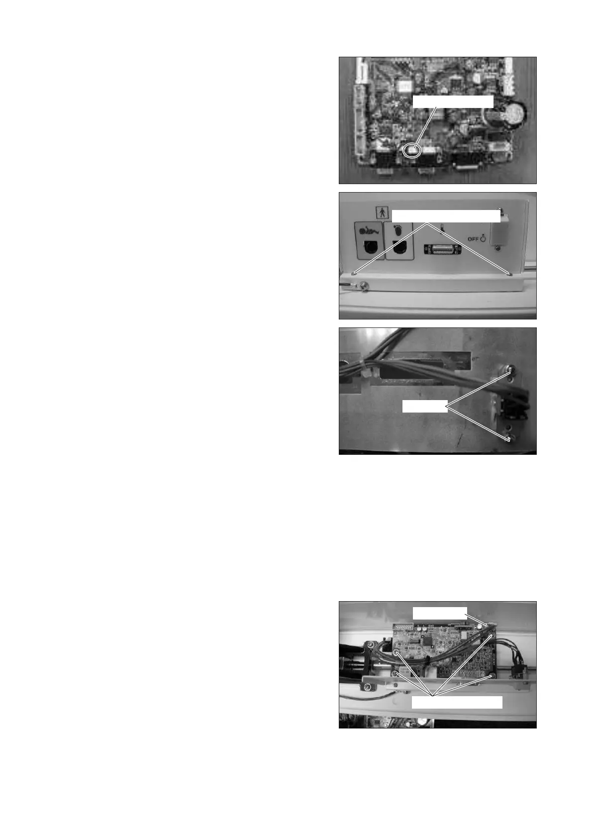
(4) Remove the plate.
Remove the two tapping screws (M3 x 10) with a
Phillips screwdriver.
Tapping screw (M3x10)
Nut (M3)
(5) Remove the power switch.
Remove the two nuts (M3) with a box wrench (dis-
tance between the opposite sides: 5.5mm).
(6) Reassembly: Reassemble in the reverse order of dis-
assembly.
6-3-7. Replacing the Detection Board
(1) Remove the control box cover.
See (1) ~ (3) in “6-3-5. Replacing the Control Box
Cover.”
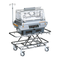
(2) Remove the detection board.
Remove the connector (JD1) from the detection
board and then remove the four sems screws (M3 x
8) with a Phillips screwdriver.
Sems screw (M3x8)
Connector
(3) Reassembly: Reassemble in the reverse order of dis-
assembly.