Disassembly and Replacement Procedures
DISASSEMBL
Y
AND REPLACEMENT
125
Remove the coating clip on the side of the power
box plate.
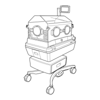
<Protective earth terminal>
Remove the five sems screws (M4 x 8) fixing the
earth terminals of the upper section of the main
body, the oxygen controller, the high temperature
sensor, the warming heater and the humidifying
heater with a Phillips screwdriver.
Pull out the power box.
Sems screw (M4x8)
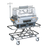
(4) Remove the rectifier board.
Remove the four sems screws (M3 x 8).
Sems screw (M3x8)
(5) Remove the capacitor cover.
Remove the two nuts (M3) with a box wrench (dis-
tance between the opposite sides: 5.5mm).
Nut (M3)
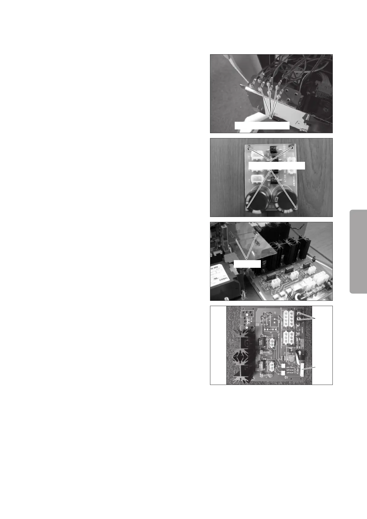
(6) Remove the heater control board (for the Incu i).
Remove the connector (JC5) from the heater con-
trol board (for the Incu i).
Remove the two terminals (JC4) from the heater
control board (for the Incu i) with a Phillips screw-
driver.
JC4
JC5
(7) Reassembly: Reassemble in the reverse order of dis-
assembly.
 Loading...