Installing the MAPD
2-18 Issue 3 May 2002
Installing the MAPD in a DC Powered Switch
Using ‘‘Worksheet A-3: Port Slot Locations for the MAPD System Assembly,’’
follow the steps below to install the system assembly.
1. Remove any existing cables from the third slot of the three contiguous slots
reserved for the MAPD system. For example, if you are going to install the
MAPD system in slots 7 through 9 of carrier A, remove the I/O cables from
slot 9. (This is the slot that provides connectivity to the TN801B MAPD
circuit pack.)
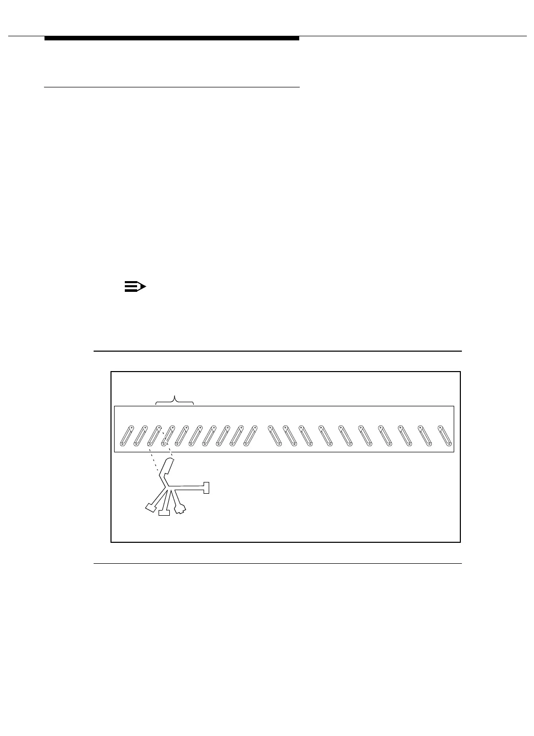
2. Connect the MAPD system assembly adapter cable to the port connector
on the back of the switch. (See Figure 2-10)
Attach the male D-type amphenol connector on the MAPD Board cable
(H600-475 G-2) to the MAPD Board (TN801B), the third slot of the MAPD
system slots.
NOTE:
You must connect this adapter cable directly to the port connector on
the switch. If you install another cable between the switch and this
cable, the MAPD system will not operate correctly.
Figure 2-10. Attaching the MAPD Cable
DCIU Male 25 Pin RS-232 (not used)
Admin/Port B
MAPD Cable (H600-475-GP2)
20 19 18 17 16 15 14 13 12 11 10
3rd 2nd 1st
9 8 7 6 5 4 3 2 1
Example of
Maint/
Female 25 Pin
RS-232
Female RJ45
MAPD Slots
RS-232
25 Pin
Female
Port A