Planning: Task 3 — Familiarizing Yourself with the
MAPD System Assembly
Issue 3 May 2002
2-11
Planning: Task 3 — Familiarizing
Yourself with the
MAPD System Assembly
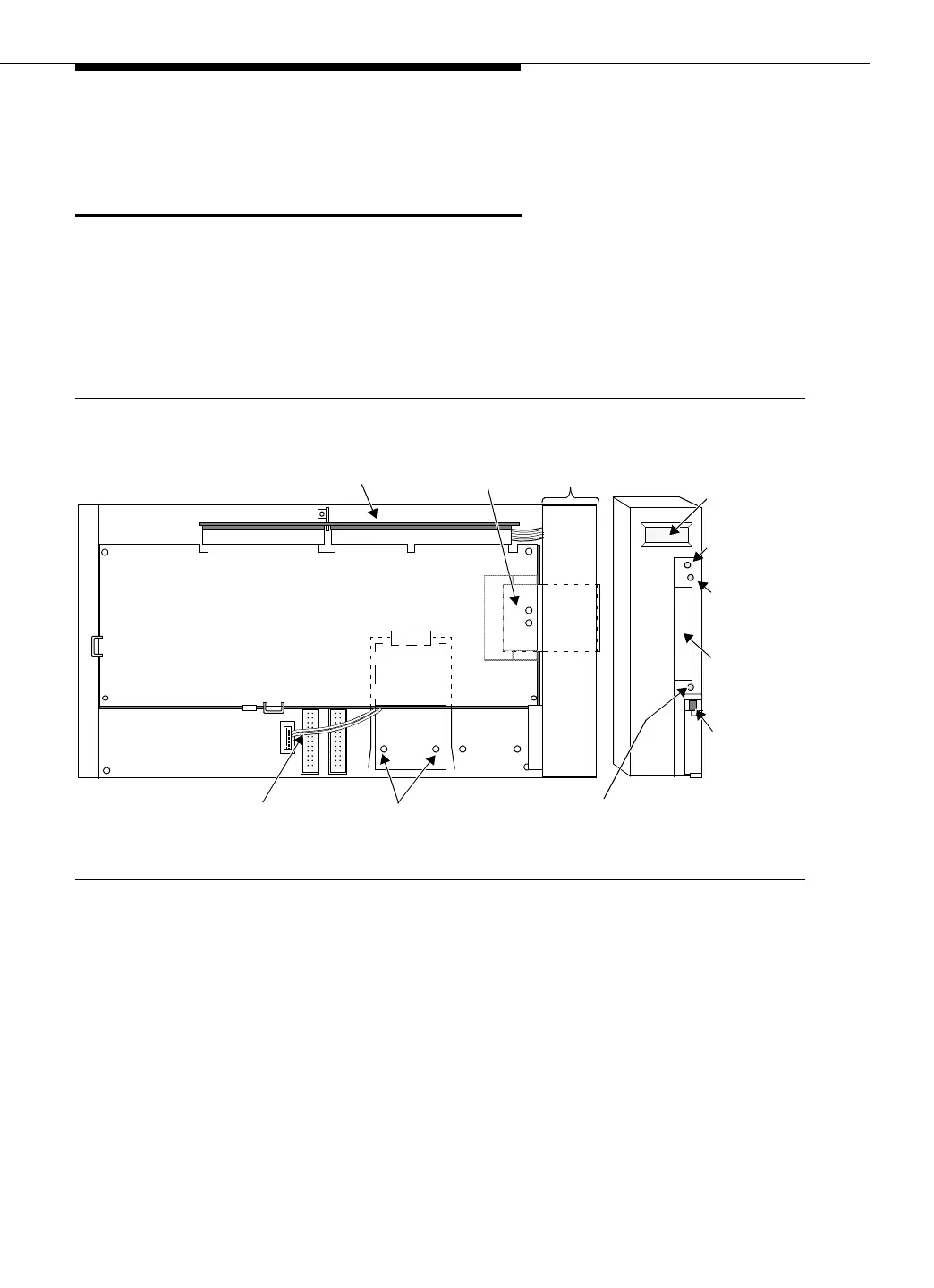
This section provides a diagram of the complete MAPD system assembly (Figure
2-6) along with a diagram of the eight-character LCD display on the front panel of
the TN801B MAPD (Figure 2-1.)
See Appendix C to be sure that all the required parts have been ordered and
shipped correctly.
Figure 2-6. MAPD System Assembly (J58890MA-1)
2-1/2”
Backside Screws
Front
Side View
Panel
TN801B Board
Side Plane
ISA ConnectorPCI Connector
for 2-1/2” Disk
PCMCIA
Pentium Processor Card
Reset Cable
(2 wires)
Front View
Disk
Drive
8 Character
LCD
Disk
Boot/Shut
Button
Board
Status
LED (red)
Slot for
PCMCIA
Disk
PCMCIA Disk
In Use LED (yellow)
Latch
TN801B