AvL Proprietary and Confidential
Content is Subject to Change without Notice Page 124 of 195
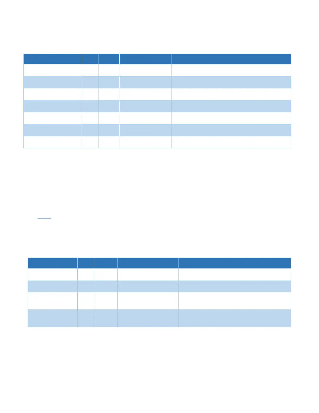
6.5.1 Acquisition
Azimuth scanning maximum velocity used in scanning
movements.
Elevation scanning maximum velocity used in scanning
movements.
Scan Polarization Velocity
Polarization scanning maximum velocity used in scanning
movements.
Slow Scan Azimuth Velocity
Azimuth slow scanning maximum velocity used in scanning
movements.
Slow Scan Elevation
Velocity
Elevation slow scanning maximum velocity used in scanning
movements.
Slow Scan Polarization
Velocity
Polarization slow scanning maximum velocity used in
scanning movements.
Peaking Ignore Noise Level
Select “Yes” to ignore calculated noise. Select “No” to only
peak on signal changes greater than the noise.
These Scan Velocity parameters set the maximum speed that each axis is allowed to move when the
indicated scan speed is used by the AAQ.
Speeds should be selected with the delay and response time of the device in mind. For example, if
the device’s signal output level is slow to respond to actual changes in signal level, then setting a
relatively slow scan speed is advisable. If scan speed is set too slow, acquisition time will lengthen
unnecessarily.
Note - Picking a value above the actual maximum speed of any axis will result in
motion at the actual maximum speed and will have no detrimental effect to
the system.
6.5.2 Coarse Peaking
Number of cycles to complete for coarse peaking. ( 0=1
Az only, 1 = 1Az and 1 El only )
Coarse Peaking
Maximum Cycles
Maximum number of cycles to complete before Coarse
Peaking stops.
“None”, “Cross Pattern”,
“Step Pattern”, Plateau
Peaking
The peaking method to use for Coarse Peaking routines
Coarse Peak Signal
Difference Threshold
The amount of signal difference between peaking
iterations that will satisfy the system as the signal is
peaked.
Coarse peaking cycles sets the minimum number of cycles that will be completed in the Coarse
Peaking process regardless of any improvement made in antenna pointing (received signal level) at
the completion of each cycle.