EasyManuals Logo

AvL Technologies AAQ Antenna Controller User Manual

AvL Technologies AAQ Antenna Controller
195 pages
To Next Page IconTo Next Page
To Previous Page IconTo Previous Page
Page #28 background imageLoading...
Page #28 background image
AvL Proprietary and Confidential
Content is Subject to Change without Notice Page 28 of 195
3.5.1 Factory Default Network Configuration
Equipment described:
AAQ Controller
Client Computer
Connection
Eth1:0 Customer Network
Eth1:1 Customer Network
Eth1:2 Service Network
IP Address
192.168.129.50
192.168.129.52
192.168.129.51
Subnet Mask
255.255.255.0
255.255.255.0
255.255.255.0
Gateway
None
None
None
Fig. 3.5.1a - Factory Network Example
The default network configuration contains basic networking needed to set up the controller on the
customer’s network. The IP addresses are set on the 192.168.129.x network.
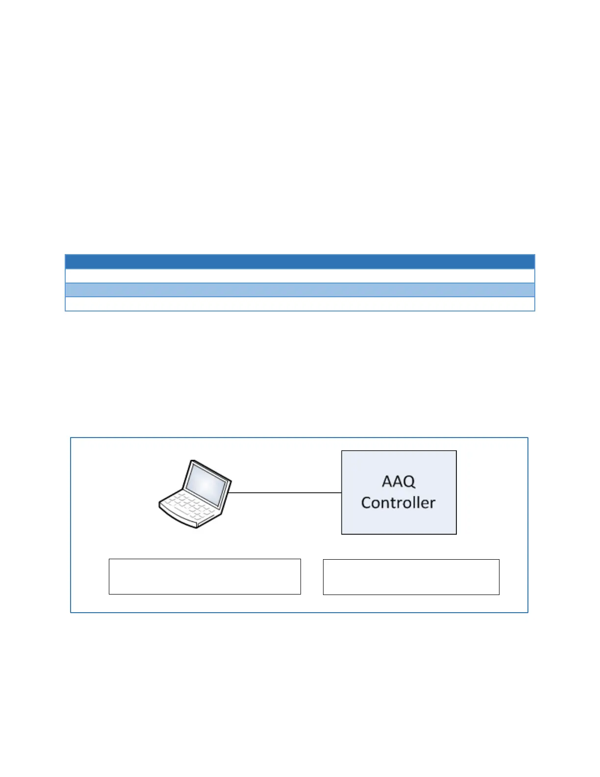
To communicate to the AAQ controller connect a computer to the controller as shown below:
Figure 3.5.1b - Simple Network Configuration Example
In the above example, the computer may be set to any address within the subnet,
192.168.129.1 through 192.168.129.254 with the exception of the controller address.
Static IP Address: 192.168.129.2
Subnet Mask: 255.255.255.0
Computer
IP Address: 192.168.129.50
Subnet Mask: 255.255.255.0
AAQ Controller

Table of Contents

Questions and Answers:

Question and Answer IconNeed help?

Do you have a question about the AvL Technologies AAQ Antenna Controller and is the answer not in the manual?

AvL Technologies AAQ Antenna Controller Specifications

General IconGeneral
BrandAvL Technologies
ModelAAQ Antenna Controller
CategoryController
LanguageEnglish