AvL Proprietary and Confidential
Content is Subject to Change without Notice Page 16 of 195
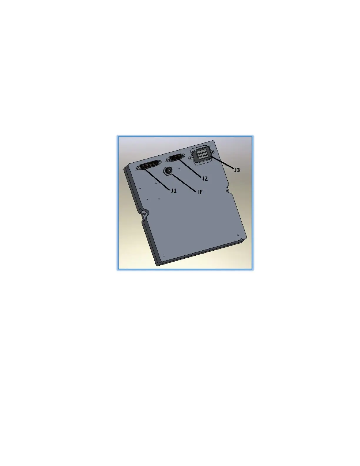
The AAQ consists of a single PCB (Printed Circuit Board) enclosed in an aluminum housing with four (4)
external connectors. The 8-pin power connector (J3) receives 28 VDC power and distributes the PWM
voltage to each of the three standard motors. The TNC coax connector (IF IN) receives RF signal from
the LNB. Two D-sub miniature connectors, one 28-pin (J2) and one 44-pin (J1) provide connection to
various sensors and other external devices, including the NAV RIOM, over serial and Ethernet. The AAQ
Enclosure is shown in Figure 2.
Figure 2.2 - AAQ Enclosure and Connectors
2.1.1 The AAQ enclosure contains:
1. CPU: ARM9 running the LINUX OS
2. Memory: 4 GB micro SD, 2 GB RAM, 4 GB NAND Flash w/battery backup
3. Servo Control: 3-axis Brushed DC Motors (EL 12A, AZ 8A, POL 5A)
4. Encoder Feedback: 3-axis quadrature encoder circuits
5. RSL: RF Signal Detector with Variable Attenuator
6. Tilt Sensor: 2-axis