AvL Proprietary and Confidential
Content is Subject to Change without Notice Page 126 of 195
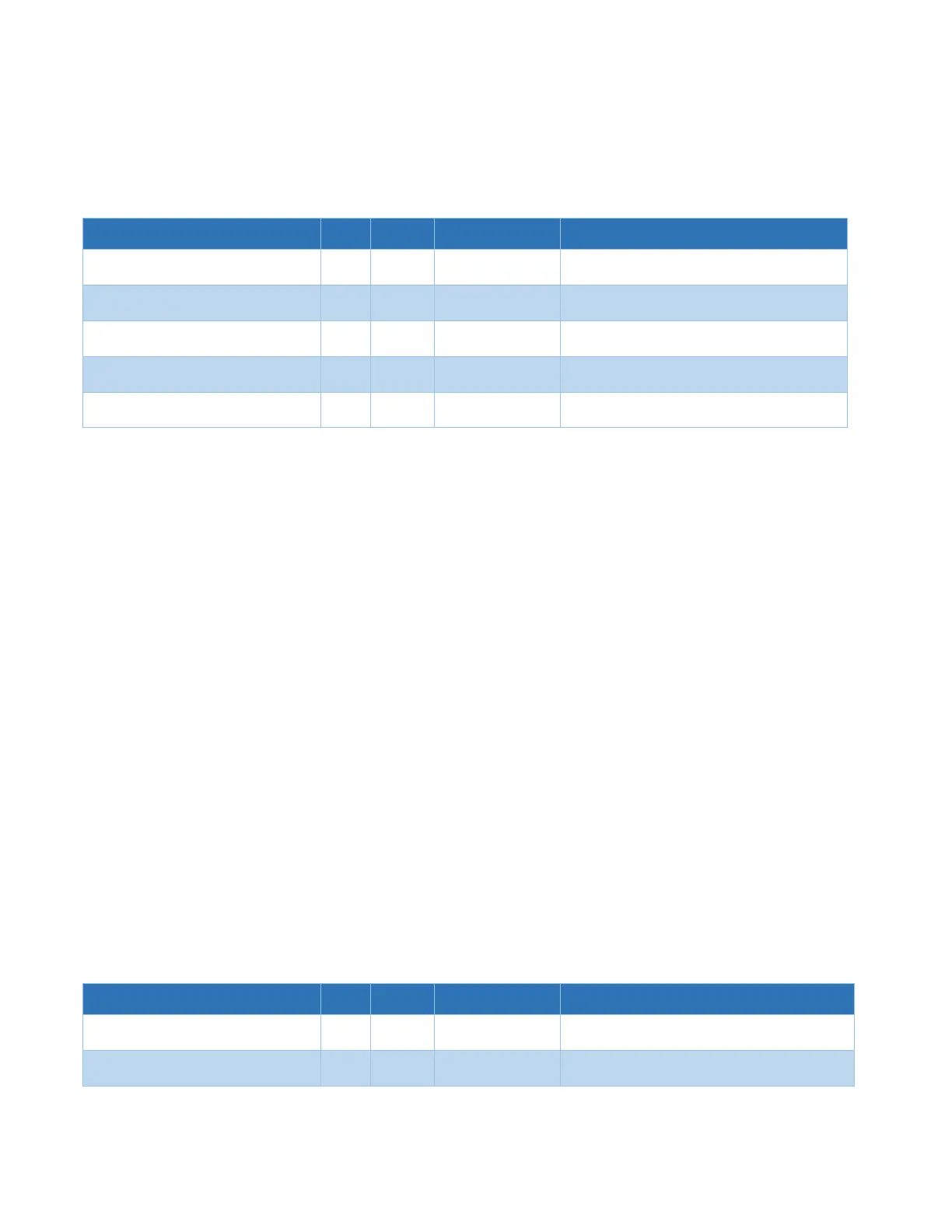
6.5.4 Cross Pattern - Coarse Peaking
Cross Pattern Coarse Peaking Width
Width in degrees to scan during a coarse cross
pattern peaking function.
Cross Pattern Coarse Peaking Height
Height in degrees to scan during a coarse cross
pattern peaking function.
Cross Pattern Coarse Azimuth Velocity
Azimuth velocity in degrees/sec for coarse
peaking.
Cross Pattern Coarse Elevation
Velocity
Elevation velocity in degrees/sec for coarse
peaking.
Cross Pattern Coarse Signal Tolerance
Signal degradation amount before a scan
stops.
Coarse Cross Peaking is the standard method used by the AAQ for Coarse Peaking on the received
satellite signal.
The Cross Pattern Coarse Peaking parameters set the total AZ width and EL height of the “cross” that
will be scanned. These parameters should be set sufficiently large enough to insure that Coarse Peaking
is not performed in a side lobe of the antenna beam. However, making them overly large will add time
to the overall Acquisition process and increase the chance that the signal from a stronger neighboring
satellite will be used for Coarse Peaking.
The Cross Pattern Coarse Velocity parameters specify the speed that the antenna will move in each
direction during the signal level measurement scans. As was true for the Scan Velocity parameters, the
possibly sluggish response time of the Signal Source and the desire for short Acquisition times must be
considered.
Cross Pattern Coarse Signal Tolerance sets a tolerance on acceptable signal drop between coarse
peaking cycles. This is also used to set plateau levels when using Plateau Peaking.
Cross Pattern Fine Signal Tolerance sets a tolerance on acceptable signal drop between fine peaking
cycles. This is also used to set plateau levels when using Plateau Peaking.
6.5.5 Cross Pattern - Fine Peaking
Cross Pattern Fine Azimuth Velocity
Azimuth velocity in degrees/sec for fine peaking.
Cross Pattern Fine Elevation Velocity
Elevation velocity in degrees/sec for fine
peaking.