AvL Proprietary and Confidential
Content is Subject to Change without Notice Page 15 of 195
Chapter 2 - AAQ System Architecture & Hardware Overview
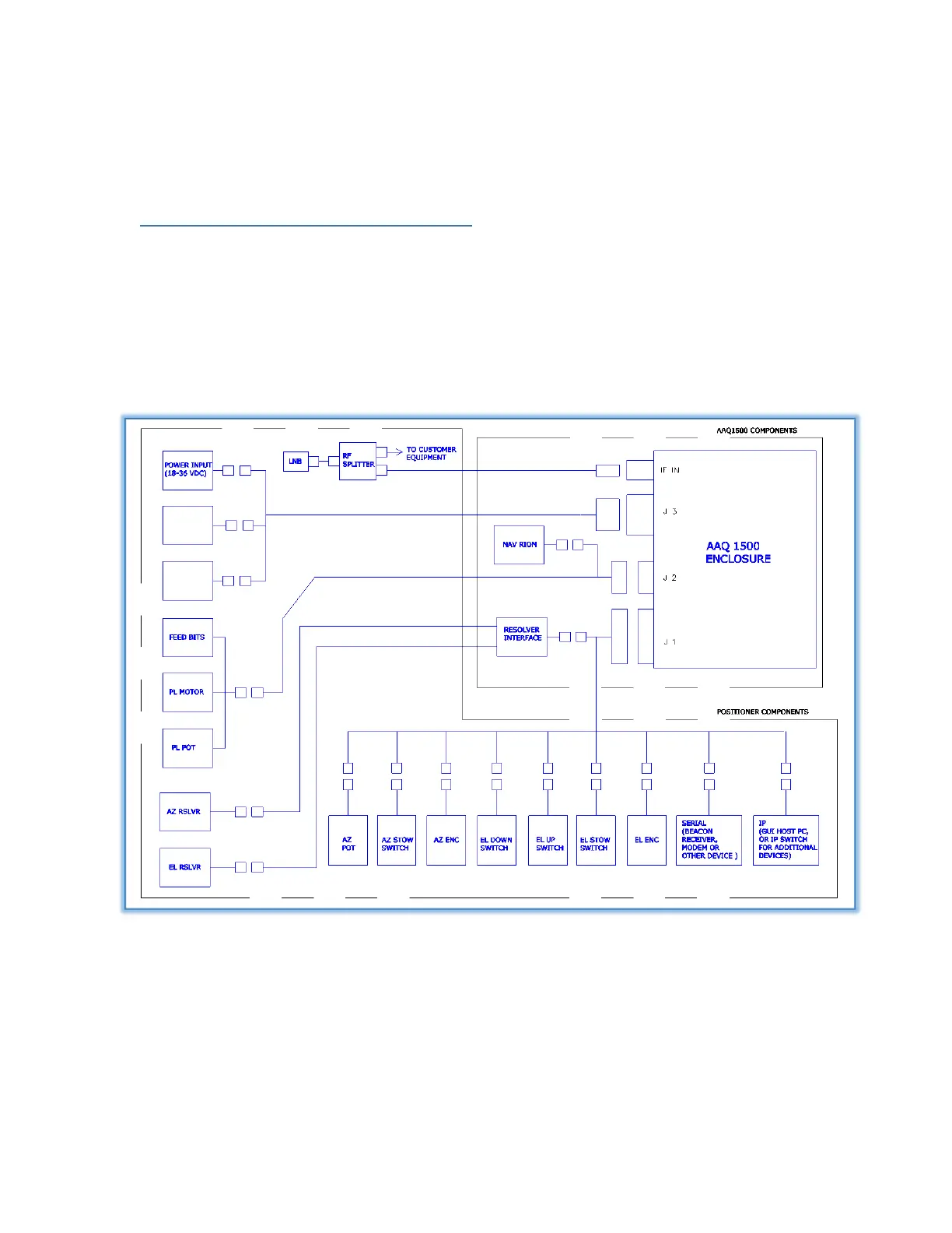
2.1 Controller System Block Diagram
The basic AAQ Controller block diagram is shown in Figure 1.1. The AAQ communicates with the motors
and NAV RIOM on an internal LAN. The ACU requires 28 VDC and communicates externally over a LAN or
WAN. The User Interface can be any combination of personal computer (custom GUI application or web
browser), 1 RU Control Interface or Hand Held Control Interface.
Figure 2.1 - AAQ Controller Hardware Components.