AvL Proprietary and Confidential
Content is Subject to Change without Notice Page 30 of 195
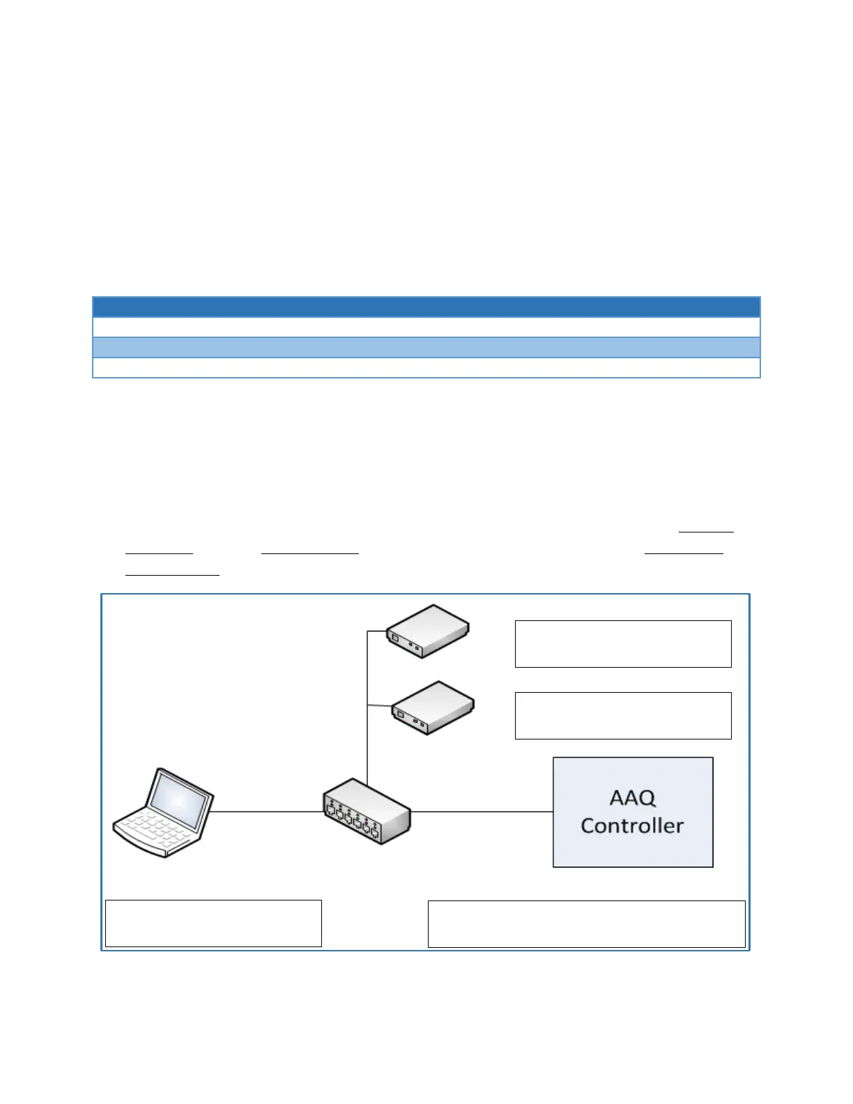
3.5.3 Dual Network Device Configuration
Equipment described:
AAQ Controller
Client Computer
Standard IPv4 Modem
Beacon Receiver
Network Switch (or CIP internal)
Figure 3.5.3a - Dual Network Device Example
In this example, the controller is tasked with communicating to two different acquisition devices,
a modem and beacon receiver. Both devices communicate using an IPv4 scheme. Both settable
controller interfaces must be used at this point, one for each device. The Eth1:0 Customer
Network interface will be set to communicate to the modem and the Eth1:1 Customer Network
interface will be set to communicate to the beacon receiver. Though each device is on a different
IP network by setting both interfaces the controller will be able to communicate to both devices
simultaneously.
Figure 3.5.3b - Dual Network Device Configuration Example
IPv4 Address: 192.168.1.2
Subnet Mask: 255.255.255.0
Network Switch (Internal to CIP)
IPv4 Address: 192.168.2.20
Subnet Mask: 255.255.255.0
IPv4 Address: 192.168.1.10
Subnet Mask: 255.255.255.0
IPv4 Address: 192.168.1.50 192.168.2.50
Subnet Mask: 255.255.255.0 255.255.255.0