AvL Proprietary and Confidential
Content is Subject to Change without Notice Page 29 of 195
3.5.2 Single Device Configuration
Equipment described:
AAQ Controller
Client Computer
Standard IP Modem (external)
Network Switch (or CIP)
Figure 3.5.2a - Single Device Example
In this example, the controller is tasked with communicating with a modem that is used as
feedback for acquisition of the satellite. The modem communicates on a standard IPv4 scheme.
One of the controller’s settable interfaces (Eth1:0 Customer Network) will be changed to
communicate to the modem on the modem’s preset or existing network. When connecting
Ethernet devices to the controller it is necessary to use the network switch contained in the CIP
so the controller can communicate with both the modem and client computer.
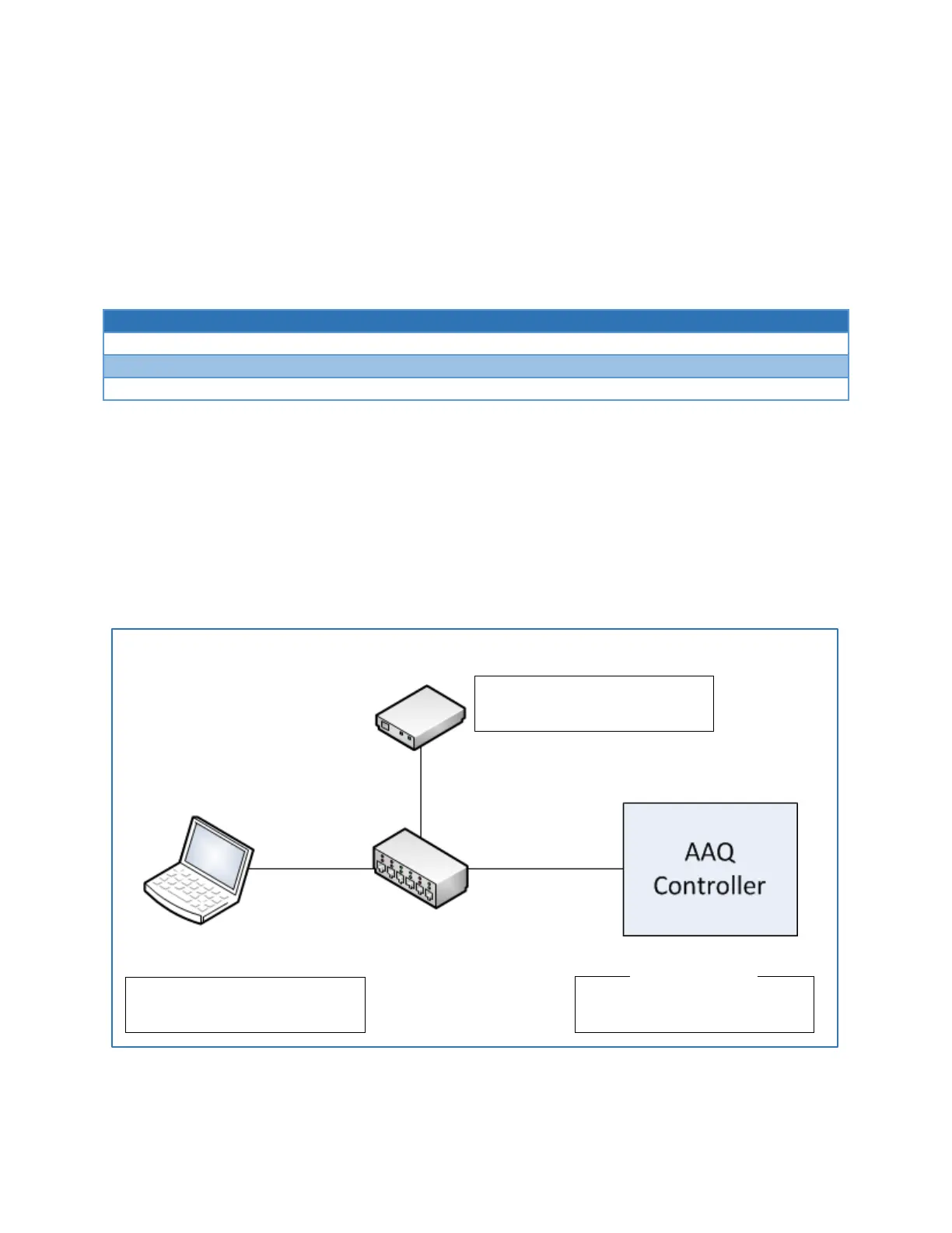
Figure 3.5.2b - Single Device Network
IPv4 Address: 192.168.1.2
Subnet Mask: 255.255.255.0
IPv4 Address: 192.168.1.10
Subnet Mask: 255.255.255.0
IPv4 Address: 192.168.1.50
Subnet Mask: 255.255.255.0
Network Switch (Internal to CIP)