AvL Proprietary and Confidential
Content is Subject to Change without Notice Page 155 of 195
7.4 AAQ Controller Functional Description
7.4.1 Pedestal Base Heading
Every AvL antenna system ships with an Electronic Compass that is used to determine an initial
heading for the antenna system’s base platform. This information, along with the antenna’s
geographic location (latitude and longitude), is essential to determine a pointing solution (antenna
pedestal azimuth, elevation, and polarization angles) for the target satellite.
This estimate of the antenna’s heading value is approximate and subject to significant variation due
to the possible presence of ferrous material, such as a metal framed building or vehicle, in the
vicinity of the antenna system. For this reason, the default value for the azimuth line scan angle
employed during acquisition is set to a value of +/- 20 degrees. In AvL’s extensive experience
supporting users of our transportable antenna systems, this value has proven to be very reliable in
the vast majority of applications.
Both the Electronic Compass and GPS are built into the AAQ’s NAV RIOM.
7.4.1.1 Navigation Remote Input Output Module (RIOM)
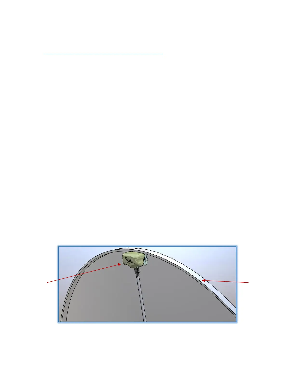
The NAV RIOM contains a GPS receiver and a 3 axis Electronic Compass and is the primary positional
sensor of the AAQ Controller. A 2-axis inclinometer also resides within the NAV RIOM. The NAV
RIOM is plugged into the AAQ’s J2 harness and it is typically mounted on the back of the reflector at
the topmost point when deployed. At this location, the GPS antenna is afforded a good view of the
sky.
Figure 7.4.1.1 - NAV RIOM on Reflector