AvL Proprietary and Confidential
Content is Subject to Change without Notice Page 139 of 195
The low backlash is achieved by the selective fit of the worm and worm gear. The gearbox contains
synthetic grease to help prevent wear in the gears. Because of the design capacity of the gearbox and
low rpm, no maintenance is required.
7.2.1.2 Azimuth Position Feedback
The directional sense of azimuth movement is defined as clockwise (CW) or counter-clockwise
(CCW), as viewed by an observer located above the antenna (aerial view or “bird’s eye”).
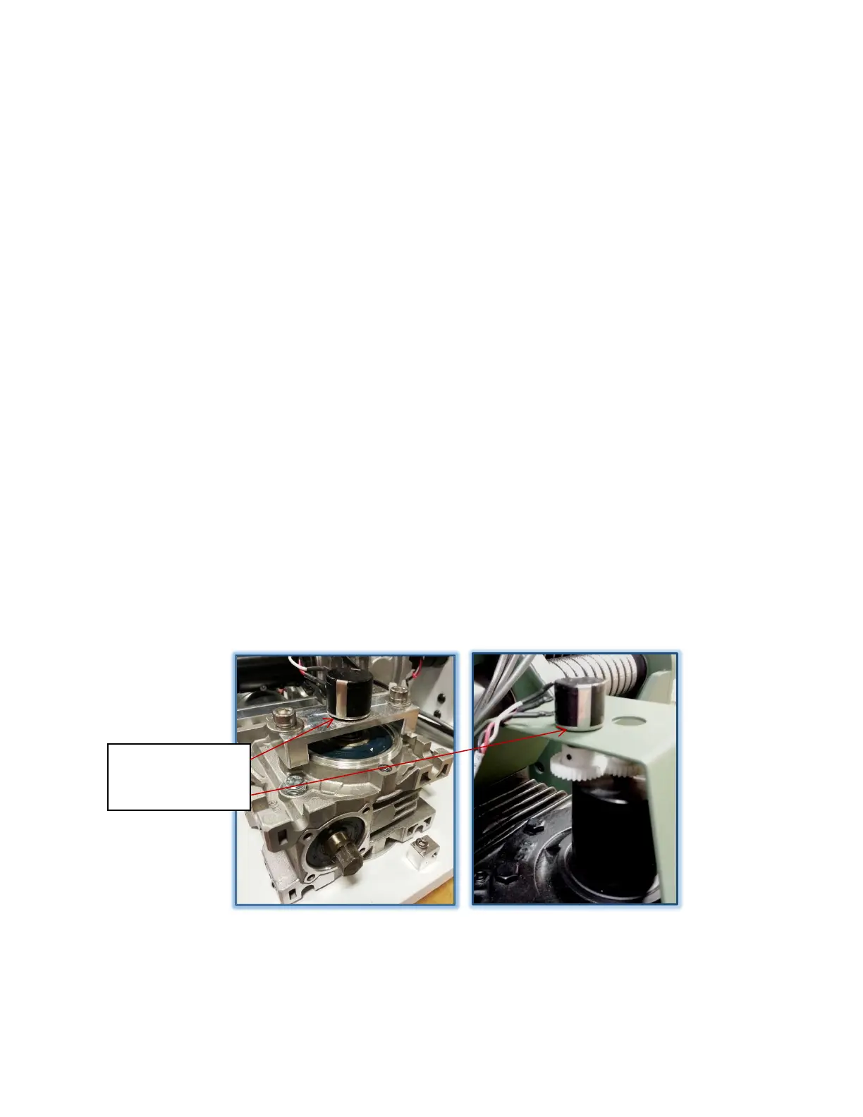
7.2.1.3 Azimuth Potentiometer (POT)
The azimuth position feedback is produced in part, by a potentiometer. The pot acts as an adjustable
voltage divider using a three-terminal resistor with a sliding contact. The pot is driven by the output
shaft of the worm gear box. Since the AvL cable drive has no backlash, the position feedback is as
accurate as the resolution and accuracy of the potentiometer along with its gear drive interface. The
potentiometer is mechanically centered at the travel position when the Az platform is in the Az stow
position or its physical center position. Limits are controlled by using inputs from the potentiometer and
optical encoder together and are set in, and controlled by, the AAQ controller.
Figure 7.2.1.3 – Az. Potentiometer Examples
Without gear drive
With gear drive