AvL Proprietary and Confidential
Content is Subject to Change without Notice Page 165 of 195
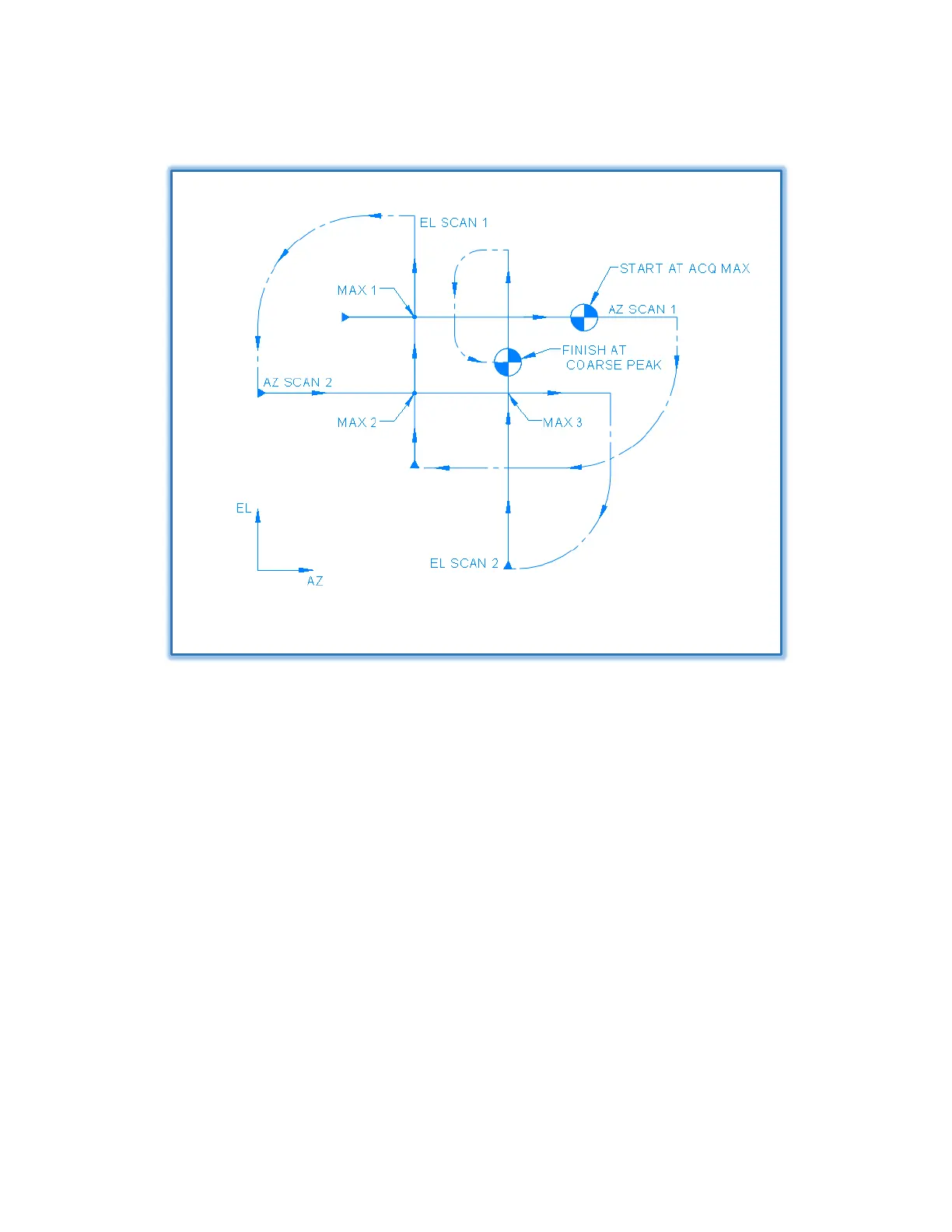
Figure 7.4.10 – Cross Scan Example
As noted in the figure, the axes of the cross scan (two orthogonal line scans) align with the antenna’s
Ped-AZ and Ped-EL axes. After the first line scan is completed, the AAQ commands the antenna to the
scan angle corresponding to maximum received signal level. The next line scan is made in the
orthogonal direction and passes through the previous scan’s maximum signal point. Again, the AAQ
commands the antenna to the scan angle corresponding to maximum received signal level seen during
the second scan. This process is repeated until Coarse Peaking success criteria are met. Those criteria
may be a predetermined number of cycles or some minimum peak signal difference between cycles.
The length of the cross scans in AZ and EL are selected to insure that the peak of the main beam will be
scanned even if the target satellite is initially acquired in a “side lobe” of the antenna. This assures that
the Fine Peaking process will be initiated when the target satellite is well within the main lobe of the
antenna’s beam.