Technical Data
Instruction handbook b maXX BM3000, BM3200, BM3300
Document no. 5.11018.11
43
of 218
3
1)
All rated values refer to a supply voltage of 230 V (single phase) and accordingly 400 V (3-phase) at 50 Hz,
a control voltage of 24 V and an environmental temperature of 40 °C.
2)
The input current must be reduced be a temperature of 40 °C and 55 °C, see correction factors at modified
environmental conditions, ZEnvir
onmental temperature– on page 31.
3)
At the rated supply voltage, the device takes up the rated-/peak-input current. At the input voltage above the
rated supply voltage, the input current must accordingly be reduced at a constant output power, see correc-
tion factors at modified environmental conditions, ZSupply voltage– on page 3
1.
4)
The output voltage is a pulsed direct current (DC). The operating range refers to the RMS value of the fun-
damental wave.
5)
The range of the output frequency is based on a stationary operation in the linear range of the PWM, i. e.
without overmodulation.
The quality of the generated output voltages depends on the ratio between output frequency and current con-
troller frequency f
I-R
( f
I-R
= 1/cycle time current controller).
The maximum output frequency f
max
, generated with high quality, is calculated as follows:
f
max
f
I-R
K
pf
--------
, typical K
Pf
18=
Furthermore the controller sets an upper limit for
the output frequency of 599 Hz (please contact the respon-
sible Baumüller sales department, keyword: export restriction).
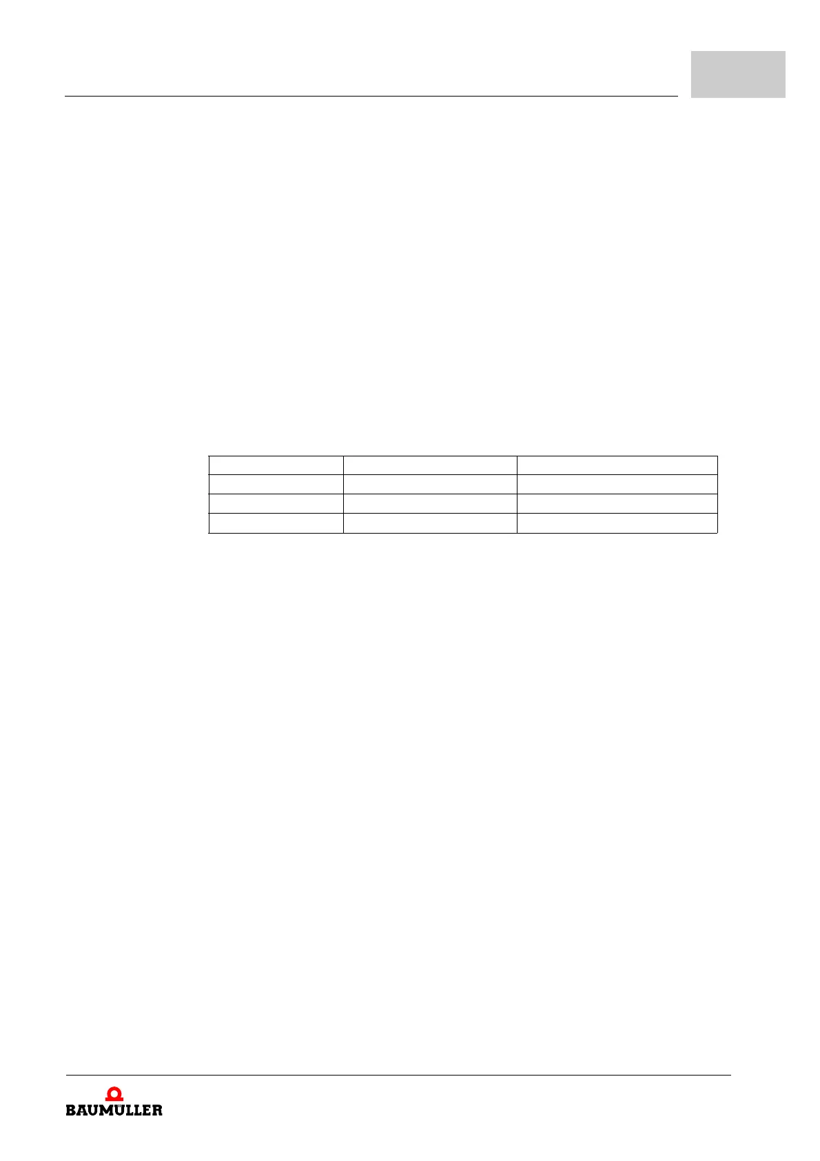
The range of the output frequency is defined as follows:
PWM frequency Current controller cycle time Range of the output frequency
2 kHz 250 µs 0 - 225 Hz
4 kHz 125 µs 0 - 450 Hz
8/16 kHz 62.5 µs 0 - 599 Hz (900 Hz
*)
)
*)
900 Hz could be generated by the controller
The device is able to generate output voltages with frequencies between f
max
and 599 Hz and the controller
allows that, however the quality of this voltages cannot be guaranteed.
Typical the devices are marked with the max output frequency at 4 kHz switching frequency: 0 ... 450 Hz.
6)
Current derating see ZFrequency-output-dependent current derating– from page 44.
7)
At a DC-link-rated voltage, the device supplies the rated-/maximum-output current. At DC link input voltages
above the rated-supply voltage, the output current must accordingly be reduced at a constant output power,
see correction factors at modified environmental conditions, ZDC-
link voltage– on page 33.
8)
The overload time is dependent of the motor current and of the heat sink temperature and is determined by
the Ixt-monitoring of the device.
9)
The continuously permitted output current must be reduced complying with ZFrequency-output-dependent
current derating– on page 44, if the statical output frequency is lower than 15 Hz and the frequency remains
between 0 and 15 Hz for over 5 seconds.
10)
The output power must not exceed the limit value of 1.5 kW, it is limited by the controller.