Display- and operating elements BM3200, BM3300
Instruction handbook b maXX BM3000, BM3200, BM3300
Document no. 5.11018.11 Baumüller Nürnberg GmbH
58
of 218
4.5
4.5 Display- and operating elements BM3200, BM3300
Depending on the variant of the fieldbus connection
EtherCAT
®
Type code BM3200, BM3300 with EtherCAT
®
CoE profile:
BM3XXX-XXXX-XXXXX[-X]-1XXXX[-S0X]-X
X[-XX][-EXX][-#XX]
Type code BM3
200, BM3300 with EtherCAT
®
SoE profile:
BM3XXX-XXXX-XXXXX[-X]-7XXXX[-S0X]-X
X[-XX][-EXX][-#XX]
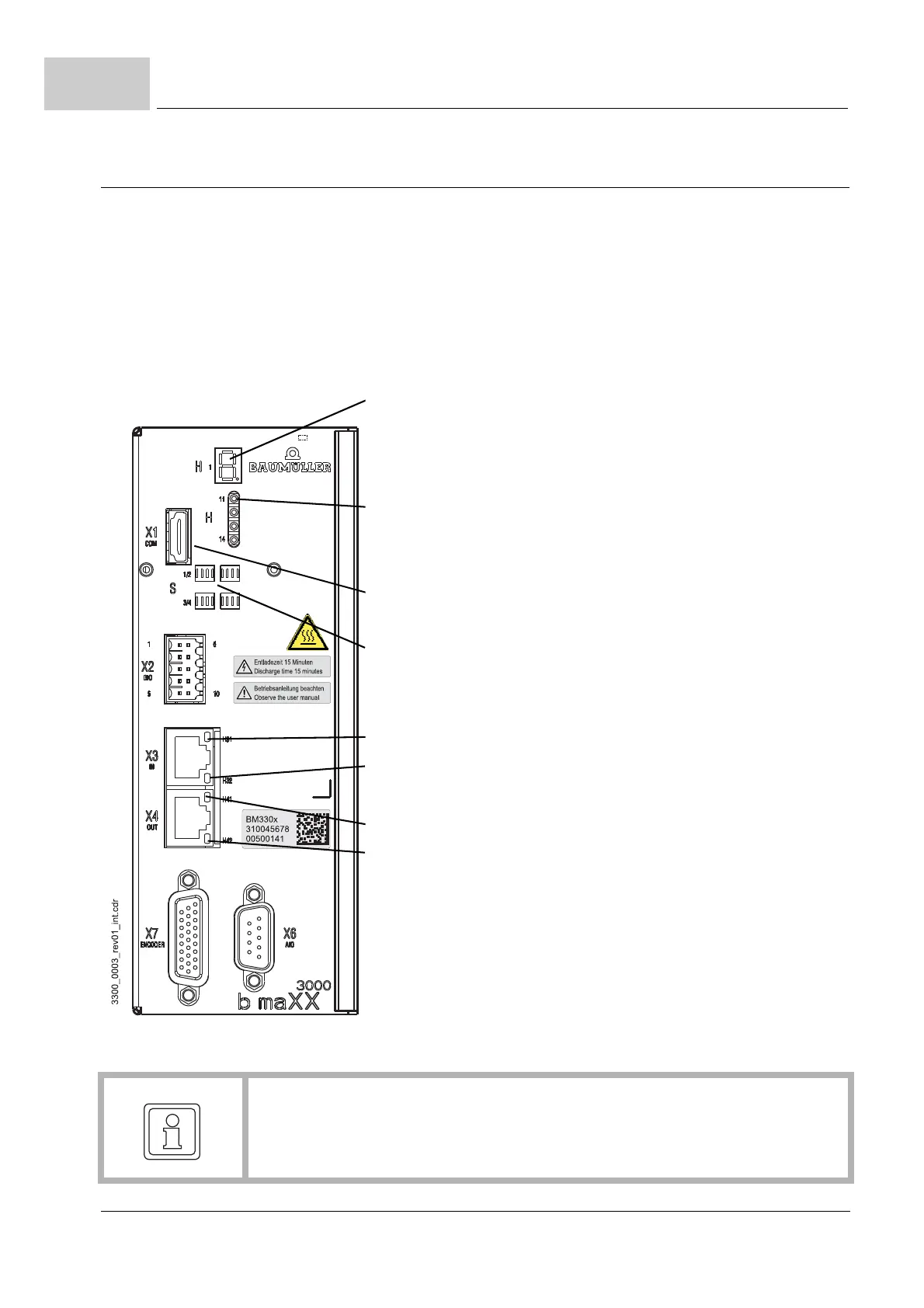
Figure 20: Display-/Operator controls Controller BM3200, BM3300 EtherCAT
®
H1: 7-segment display
display status controller
Meaning see: ZFunction of the 7-segment display–
from page 62
H11 - H14: Status display via LED
Meaning see: ZFunction of the LEDs H11 to H14– on
page 63
X1: Service interface
S1 - S4: Address switch
Setting: see
ZSettings address switches– from page 66
H31:LED EtherCAT
®
H32:LED EtherCAT
®
H41:LED EtherCAT
®
H42:LED EtherCAT
®
Meaning: see ZLEDs EtherCAT
®
– on page 64
NOTE!
Th
e service interface X1 must be used with the service cable BM5-K-USB-XXX only,
maximum transmission rate 920 kBaud.