7-1
7 DATA INPUT
Tracker IIIC has no internal GPS receiver and so requires a data input from a separate GPS or
LORAN unit in order to function in Map Mode. If required, the Skymap IIIC can also be run in Tracker
mode using an external GPS or LORAN unit. (Refer to Data In/Out in the Setup Screens Section of
the Manual). The following text is valid for Skymap IIIC also if set to Tracker mode.
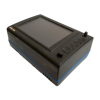
Your Tracker IIIC unit is supplied complete with a power/data cable, which has red, blue, yellow and
green cores and a braided screen. The red and blue cores are for connection to an external DC
power supply rated between 10V and 33V. The yellow core is the data input cable for connection to
your GPS or LORAN.
To operate correctly Tracker IIIC requires a 1200, 4800 or 9600 baud NMEA 0183 data sentence
containing latitude, longitude, track, and ground speed information. This can take the form of a single
RMC sentence or a combination of GGA and VTG sentences. Alternatively a 1200, 4800 or 9600
baud Trimble TNL, Garmin AIU or King equivalent ARNAV R-30 sentence may be used. A third
alternative data input is the Northstar M3 binary data format at 1200 baud.
To connect the Tracker IIIC to the GPS or LORAN source unit strip the outer cable insulation back a
short way and pull back the screening braid to reveal the four inner plastic covered cores. The
screening braid of the cable should be twisted into a single core. The red and blue cables should be
connected to an external power supply (red is +ve). The screening braid and blue cable core should
be connected to the same –ve power supply as the GPS/LORAN. This provides a return path for the
data output. You are now ready to make data connection to your GPS or LORAN unit. The input is
RS232, RS422 and NMEA 0183 compatible.
When connecting to an RS232 or NMEA device, yellow should go to DATA OUT (A line). When
connecting to an RS422 device, yellow should go to TX-. Do not connect to RS422 TX +.
Example 1: To connect to a Bendix/King KLN89/89B (RS232)
, connect the yellow core of the Tracker
IIIC cable to pin 2 of the KLN device. Connect the blue core and screen of the Tracker IIIC cable are
connected to the to the same –ve supply or A/C ground as pin 14 of the KLN device.
Example 2: To connect to a Bendix/King KLN90/90B (RS232)
, connect the yellow core of the Tracker
IIIC cable to pin 13 of the KLN device. Ensure the blue core and screen of the Tracker IIIC cable are
connected to the to the same –ve supply or A/C ground as pin 27 of the KLN device.
Example 3: To connect to a Garmin GPS150/155 (RS232)
, connect the yellow core of the Tracker IIIC
cable to pin 19 (channel 1) or pin 24 (channel 2) of the Garmin device. Ensure the blue core and
screen of the Tracker IIIC cable are connected to the to the same –ve supply or A/C ground as pin 26
of the Garmin device.
Example 4: To connect to a stand-alone Pronav or Garmin GPS 100 (NMEA)
, connect the yellow core
of the Tracker IIIC cable to the yellow core of the power/data cable. Ensure the blue core and screen
of the Tracker IIIC cable are connected to the same –ve supply or A/C ground as the black core of the
power/data cable of the GPS.
Once you have made the physical connection to your GPS or LORAN it is essential to select an
appropriate data output. This can be done by referring to the manual for your GPS/LORAN and
choosing an option that corresponds to one of the compatible data input types listed above.
Once a suitable data output type has been selected on your GPS/LORAN and it has a fix, switch on
your Tracker IIIC and from the Main Menu Screen, press Key 1, DATA IN/OUT. Screen 35(T), Data
input/output Setup and Test Screen will be displayed.