SENSseries LB 480 Level measurement
BERTHOLD TECHNOLOGIES GmbH & Co. KG
2 – 215
Volume 2 2 Installation
2
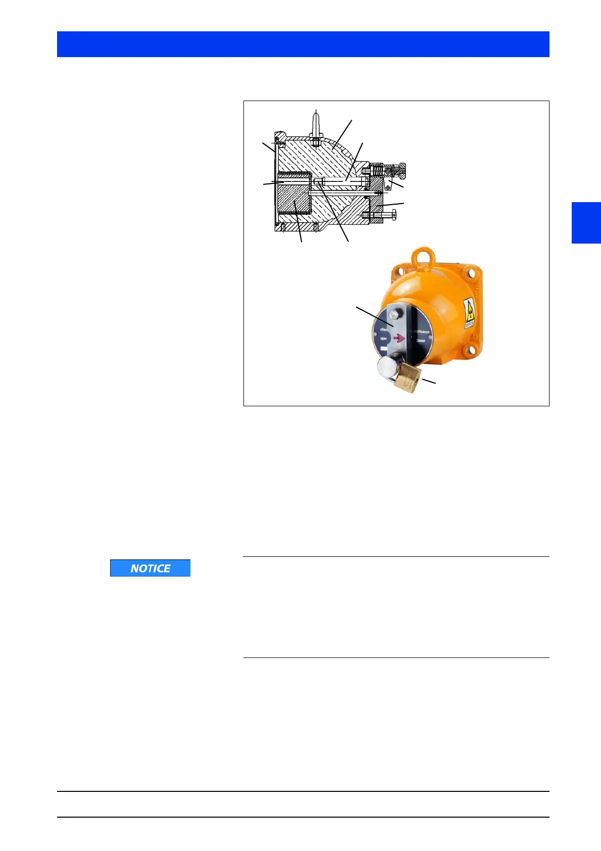
Fig. 2-41 Cross-section drawing and photo of the point source shielding,
top: beam channel open, bottom: beam channel closed
Turning the lever (4) will also rotate the locking core and open the
source exit channel towards the detector. The arrow on the lever is
pointing to "OPEN".
The source exit channel must be closed during transportation,
during installation and while carrying out work on the vessel. The
arrow on the lever is pointing to "CLOSED". In the "OPEN" and
"CLOSED" position, the lever or the locking core are protected by a
padlock.
Function failure due to damage
The detector fixture must not transfer any vibrations or heat onto
the shielding; otherwise the locking mechanism may be damaged
and the shielding effectiveness may be adversely affected.
Therefore, install the fixture on a vibration-free support or attenu-
ate possible vibrations using vibration absorbers. Prevent heat
transfer by using suitable insulating materials.
1
1 Shielding
2 Source fixture
3Padlock
4 Locking bolt
5 Point source
6 Locking core
7 Beam channel
8 Cover plate, front
2
3
4
56
7
8
3
4